Software Engineering
| Created by | Borhan |
|---|---|
| Last edited time | |
| Tag | Year 3 Term 2 |
Resources
- Slide from ma’am (https://github.com/borhan008/academic_files/tree/main/3-2/5.%20Software%20Engineering%20and%20Information%20System%20Design/Slides)
- Atkia apu’s note
- Mahir Labib Dihan sir’s note,(https://drive.google.com/file/d/1d_XuqXV4zqYAv8yN8puBCQNll_zcw1jl/view)
- Diagrams
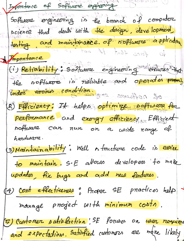
Software Engineering is an engineering branch associated with development of software product using well-defined scientific principles method and procedure.
| Aspects | Software Engineering | System Engineering |
|---|---|---|
| Definition | Software Engineering is an engineering branch associated with development of software product using well-defined scientific principles method and procedure. | System engineering isa an interdisciplinary field that focuses on integrating and managing complex system. |
| Scope | Focuses on software components | Holistic approach to entire system |
| Objective | To develop, maintain and improve software product | To ensure system functionality and integrating various parts |
| Method | Scrum, Agile, Devops | MBSE |
| Deliverable | Software Application | Fully functional system |
| Application | IT and Software Industry | Broad application in aerospace, automobile |
| Stakeholder Interaction | Software users, developers and IT Personals | A broader range of stakeholders from various fields |
| Aspect | Software | Program |
|---|---|---|
| Dependency | Software is mainly dependent on the operating system. | Programs are mainly dependent on the compiler. |
| Categories | Various software categories include application software, system software, computer programming tools, etc. | There are no such categories of programs. |
| Size | The size of software generally ranges from megabytes (Mb) to gigabytes (Gb). | The program size generally ranges from kilobytes (Kb) to megabytes (Mb). |
| Developer Expertise | Software is usually developed by people having expert knowledge and experience as well as are trained in developing software and are also referred to as software developers. | Programs are usually developed by the person who is a beginner and has no prior experience. |
| Nature | Software's can be a program that generally runs on computer. | Programs cannot be a software. |
| Necessity for Computer Functionality | If software's are not present in computers, then computer is useless. | If programs are not present in computer, then also computer can function well because of operating system. |
| Download | Software's can be downloaded on computer using internet without any need of program. | Program cannot run on computer without any software present in computer. |
| Features | Features of software includes security, safety, dependability, correctness, etc. | Features of program includes reliable, cost effectiveness, maintainability, profitability, etc. |
| Development Time | It requires more time to create software than program. | It requires less time to create program than software. |
| Examples | Examples of software includes Adobe Photoshop, Google Chrome, PowerPoint, Adobe Reader, etc. | Examples of program includes Web browsers, word processors, video games, etc. |
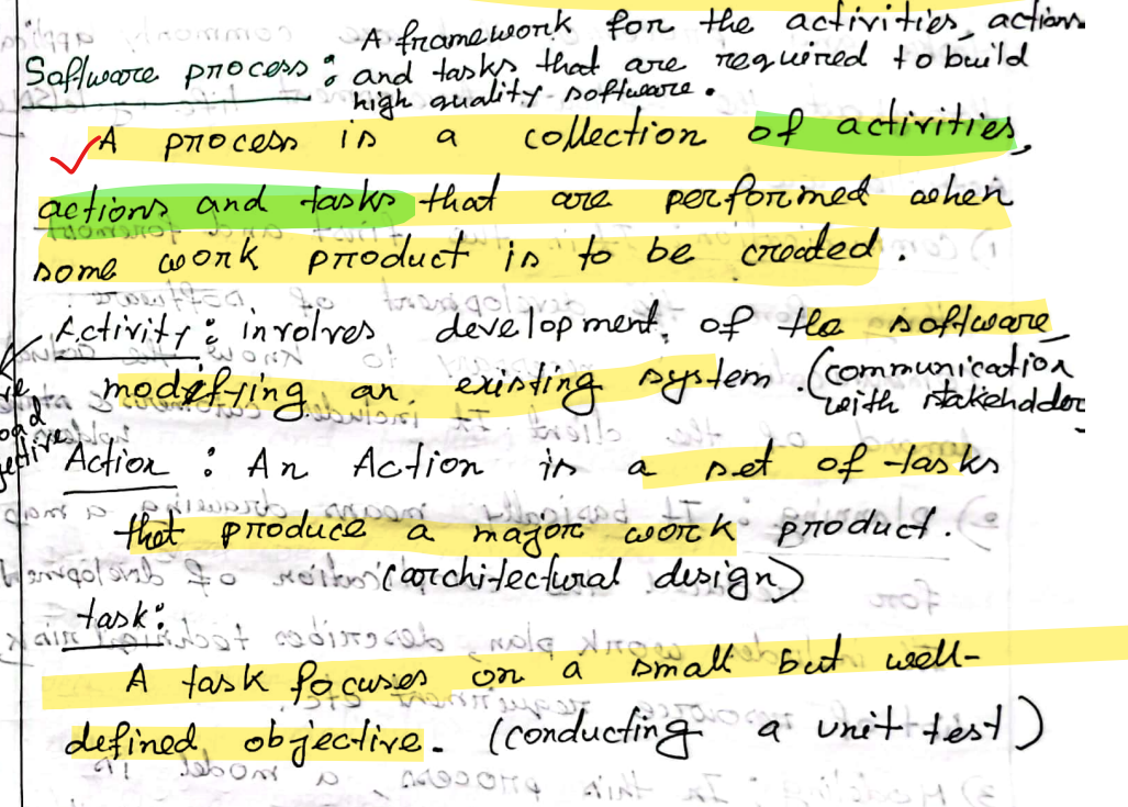
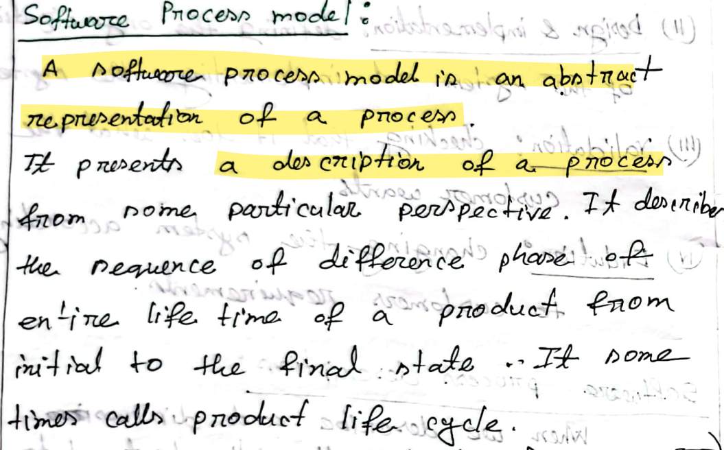
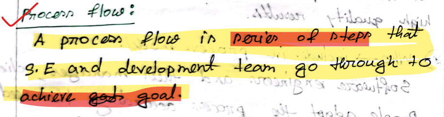
A software process framework is a collection of task sets.
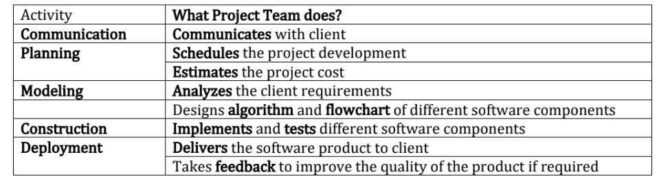
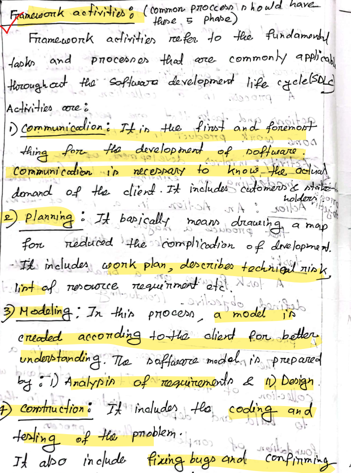
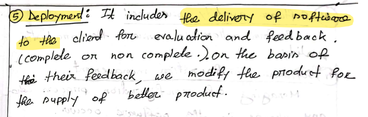
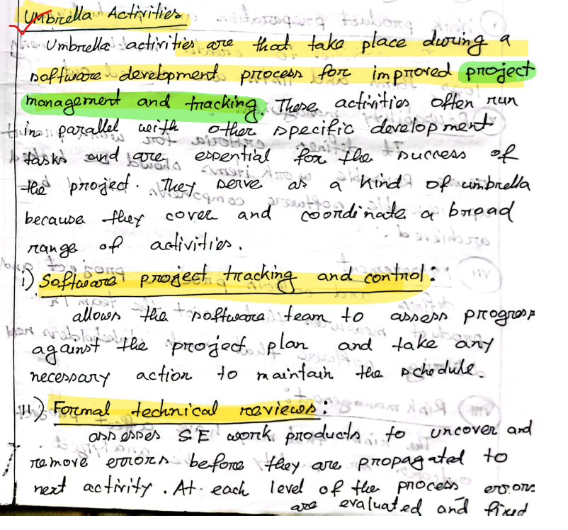
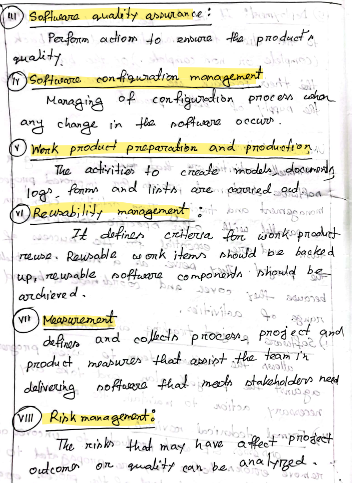
Common Activities in software processes
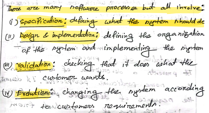
Generic Process model activities
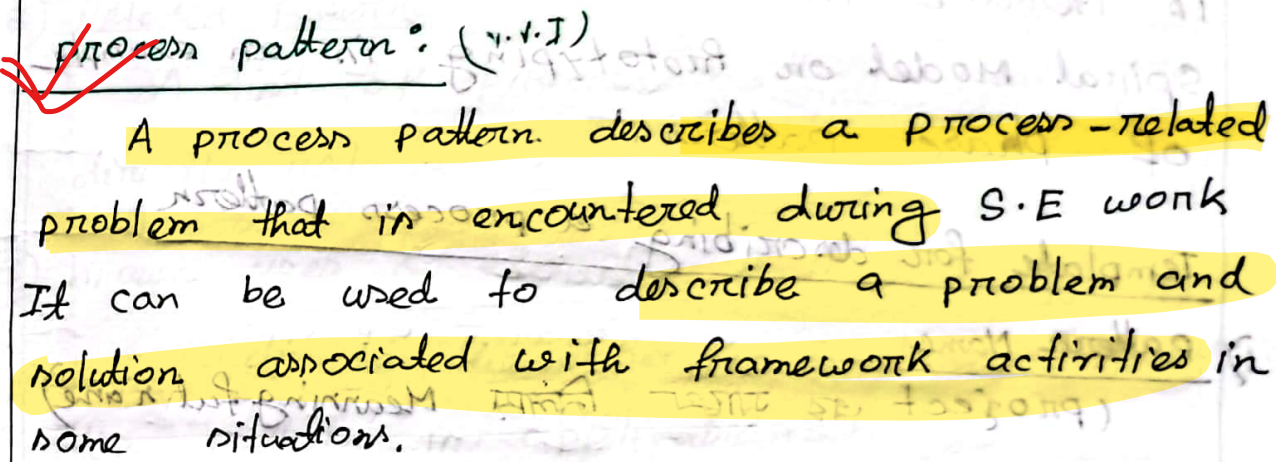
Types of process pattern:
- Task Pattern : Problems associated with a software engineering action or work task and relevant to successful SE proactive are defined by task pattern. Example: Requirement gathering.
- Stage pattern: problems associated with a framework activity for a process are described by stage pattern. Example : Establishing communication
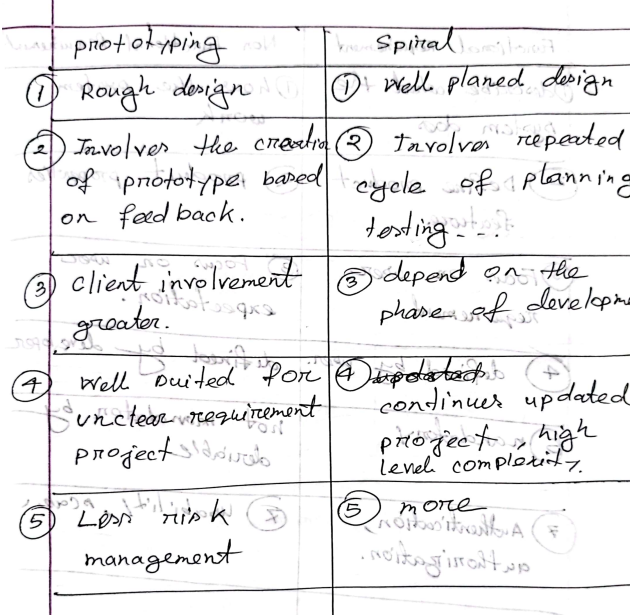
- Phase Pattern: Phase pattern defines the sequence of framework activities that occur with the process, even the overall of activities are iterative in nature. Example : Spiral Model or Prototyping
Template for describing process pattern
- Pattern name: meaningful
- Intent : Objectives
- Pattern type:
- Initial Context : pre-requisite or conditions
- Problems :
- Solution:
- Resulting context
- Related pattern
- Known uses & example
Example from GFG:
Pattern Name: Prototyping Model Design
Intent: Requirements are not clear. So aim is to make an model iteratively to solidify the exact requirements.
Type: Phase Pattern
Initial Context: Before going to the prototyping these basic conditions should be made
1. Stakeholder has some idea about their requirements i.e. what they exactly want
2. Communication medium should be established between stakeholder and software development team to ensure proper understanding about the requirements and future product
3. Initial understanding about other factors of project like scope of project, duration of project, budget of project etc.
Problem: Identifying and Solidifying the hazy and nonexistent requirements.
Solution: A description of the prototyping should be presented.
Resulting Context: A prototype model which can give a clear idea about the actual product and that needs to be agreed by stakeholder.
Related Patterns: Requirement extraction, Iterative design, customer communication, Iterative development, Customer assessment etc.
Known Uses & Examples: When stakeholder requirements are unclear and uncertain, prototyping is recommended.
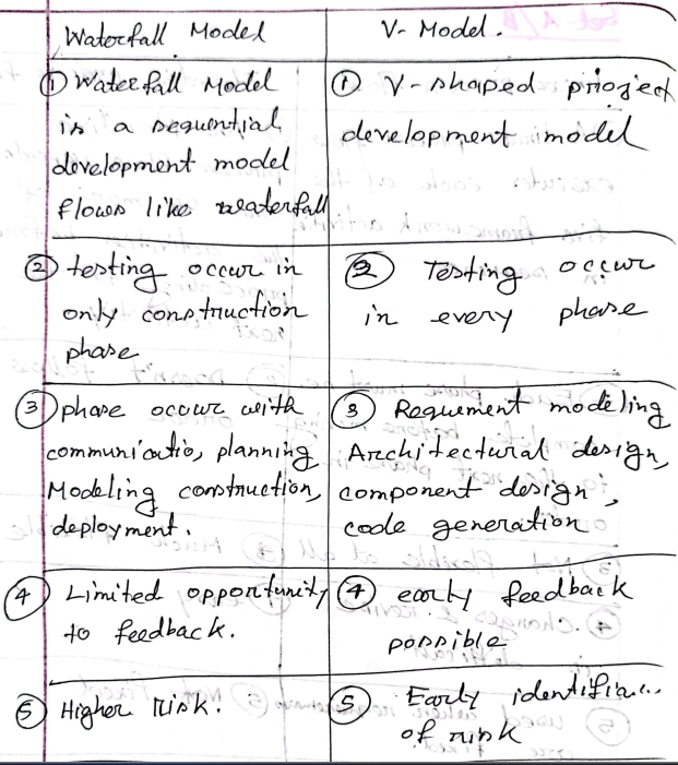
Software Development Life Cycle (SDLC) consists of the following seven stages:
- Planning: Identify the problem, assess the need for a new or alternative system, set project scope, and create a detailed project plan.
- Requirement Analysis: Gather and prioritize business requirements through collaboration between users and IT specialists.
- Design: Create technical blueprints including architecture and system models to outline how the system will function.
- Implementation: Convert design documents into actual code by building the architecture, database, and programs.
- Integration & Testing: Ensure the system meets business requirements through defined test conditions and system testing.
- Deployment: Distribute the system to users, provide training, and implement using methods like parallel, plunge, pilot, or phased approach.
- Maintenance: Provide ongoing support, fix bugs (corrective), adapt to changes (adaptive), and improve performance (perfective).
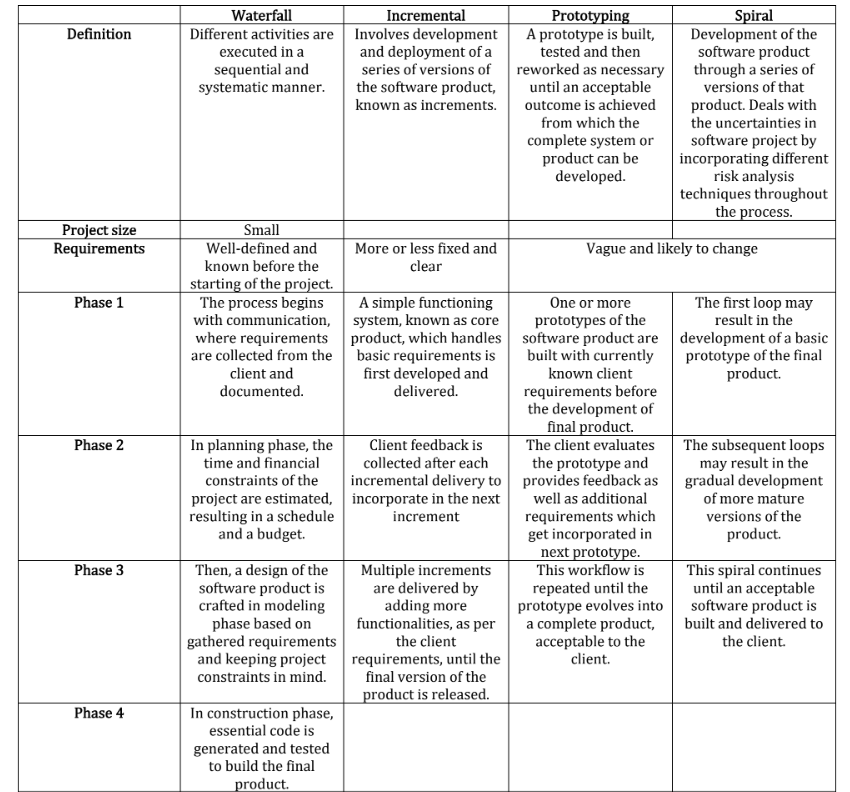
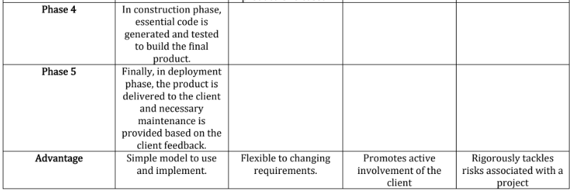
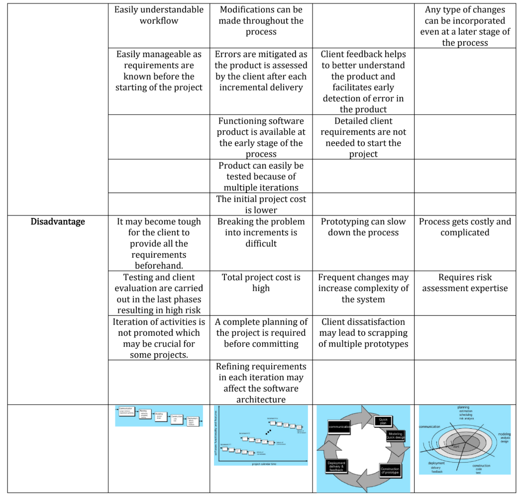
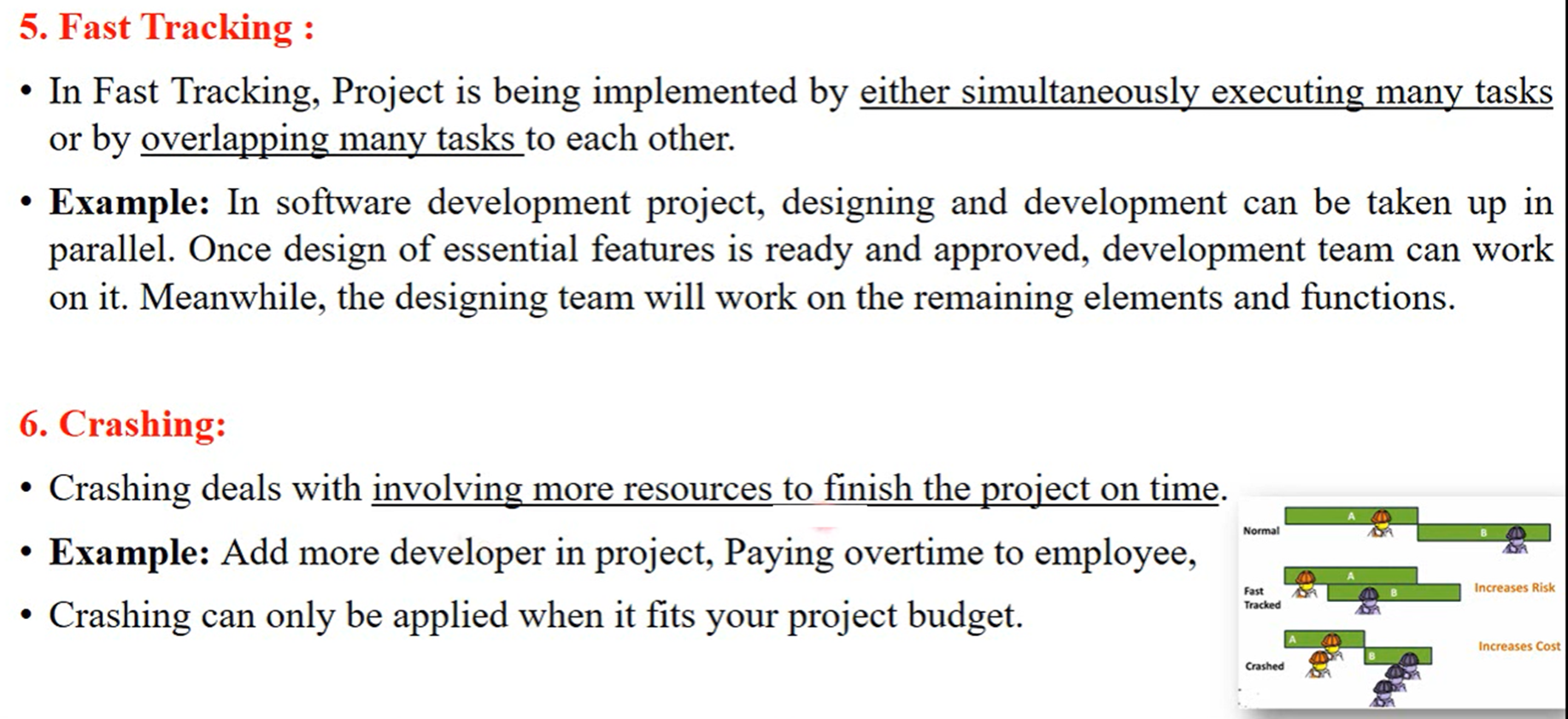
Explain how both the waterfall model of the software process and the prototyping model can be accommodated in the spiral process model. (5)
the spiral process model accommodates the waterfall model by breaking it into iterative phases and accommodates the prototyping model by allowing for the creation and refinement of prototypes in each iteration.
The waterfall model can be accommodated in the spiral process model by having each iteration represent a phase of the waterfall model. For example, the first iteration could focus on requirements gathering and analysis, the second on design, the third on implementation, and so on.
Similarly, the prototyping model can be accommodated by using the spiral model's iterative nature to create and refine prototypes in each iteration, incorporating user feedback and refining the prototype until it evolves into the final product.
Steps
i. The first loop may result in the development of a basic prototype of the final product.
ii. The subsequent loops may result in the gradual development of more mature versions of the product.
iii. This spiral continues until an acceptable software product is built and delivered to the client.
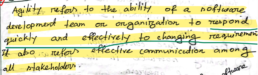
Principle: Some changes frequently bring business motivation for working sustainably through simple self-reflection
- Customer Satisfacton
- Welcome changing requirement
- frequently derliverable
- business and developer together
- supportive and motivative environemtn
- face to face conversation
- working software is the progree
- sustainable developement
- technical power and good design
- simplicity
- self organized team, best architecture, design
- the team reflects how to become more effective
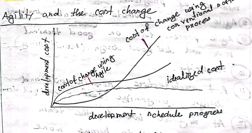
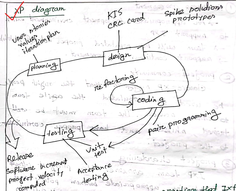
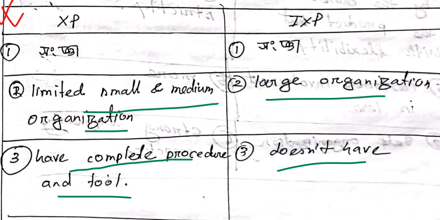
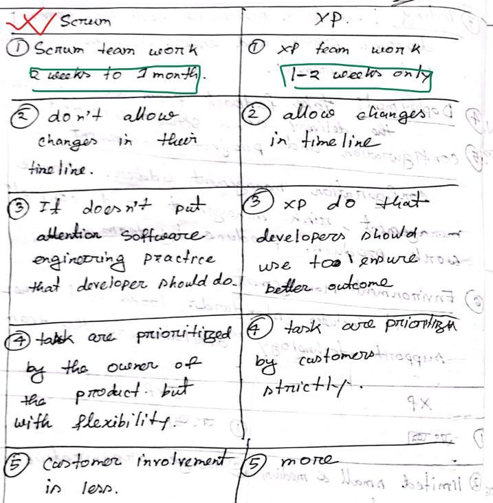
Basic activity of XP programming
- XP planning : user-stories, cost and create a release plan, delivary date, progress velocity after first increment
- XP Design : KISS, CRC card, refactoring
- Coding : Pair programming, unit test
- Testing : Unit test, Acceptance test
Industrial XP :
- Organic evolution of XP
- six practices on XP project works successfully for significant project
- Readiness assesment : development environment, skill team, support
- Project community : right people, well-trained, proper contribution
- Project chartering: business policy ensures
- Test driven management : measure criteria/metrics to progree
- Retrospective : specialized technical review
- Continuous learning
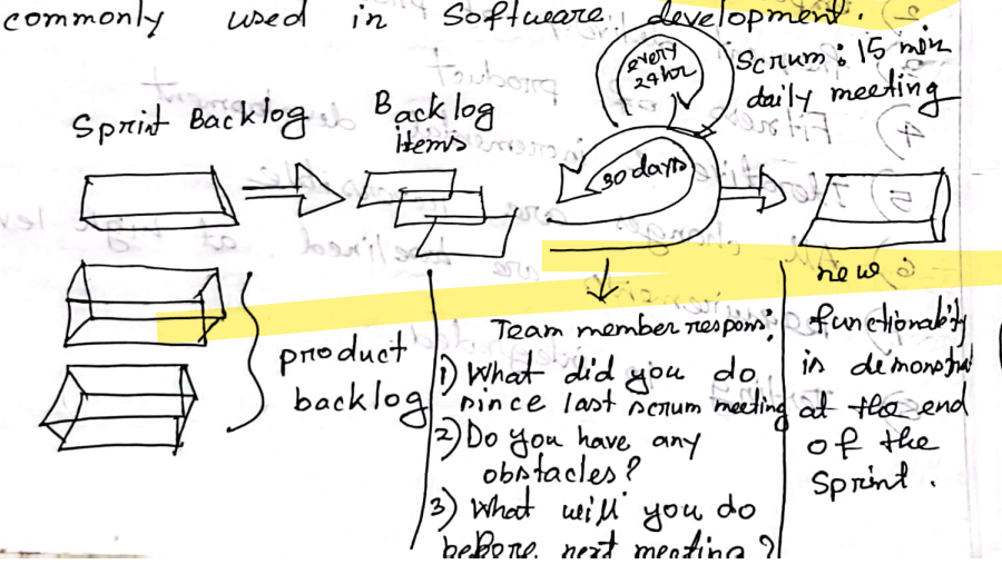
SCRUM
- Scrum prioritizes simplicity in a project and develops product in a gradual manner with frequent
delivery.
- Sprint: Planning → Implementation → Product review → Process review
- The Daily Scrum is a short, daily meeting where team members discuss progress and plan their
work for the next 24 hours.
- Advantages
- less authority and hierarcy
- adaptability
- less time to become deliverable
- more client involvement
- Disadvantages
- small project team
- 3 Questions
- What did you do since last scrum meeting ?
- do you have any obstacles?
- what will you do before next meeting ?
- Product backlog : list of features collected from customers
- Sprint backlog : prioriesed backlogs
- backlog item : sorted according to priority
- meeting : 30 days 15 mins
Requirements analysis involves understanding what the system should do, how it interacts with other systems, and what limitations or constraints exist.
Phases of Requirements Engineering
"I Enjoy Every New Software Version"
| Phase | Purpose |
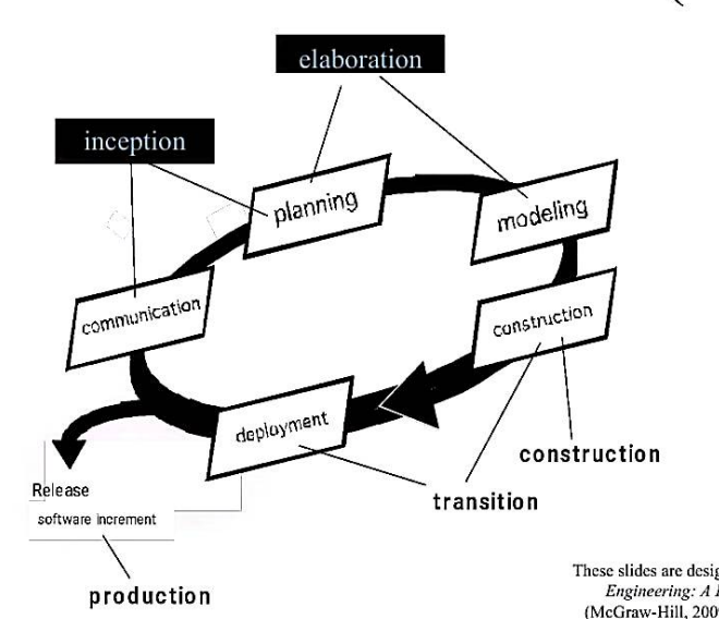
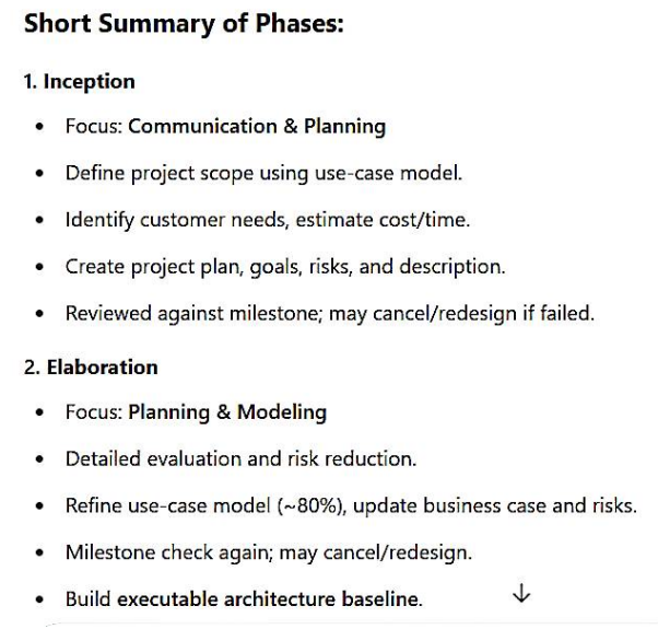
| Inception | Ask basic questions to understand: - the problem - who needs the solution - the expected solution - communication effectiveness |
| Elicitation | Gather requirements from all stakeholders (users, customers, developers, etc.) |
| Elaboration | Build detailed models to capture: - data requirements - functional requirements - behavioral requirements |
| Negotiation | Prioritize and resolve conflicts among requirements. Agree on a feasible version of the system |
| Specification | Represent requirements using: - written documents - models - mathematical formulas - use-cases - prototypes"Write More Formally Using Prototypes” |
| Validation | Review the requirements to find: - errors or misunderstandings - Clarification needed - unclear or missing information - inconsistencies - unrealistic/conflicting expectations"Every Cat Might Ignore Rain” |
🗂️ Types of Requirements
| Type | Explanation |
| Business Requirements | High-level goals, objectives, and needs of the organization. |
| Stakeholder Requirements | Expectations and needs of each stakeholder group (users, customers, etc.). |
| Solution Requirements | Specific features and functions that the system must include. |
| → Functional Requirements | What the system should do (features, user interactions, business rules). |
| → Non-Functional Requirements | Qualities the system should have (performance, security, reliability, etc.). Also called quality attributes. |
| Transition Requirements | Requirements needed for moving from the current system to the new one (e.g., data migration, training). |
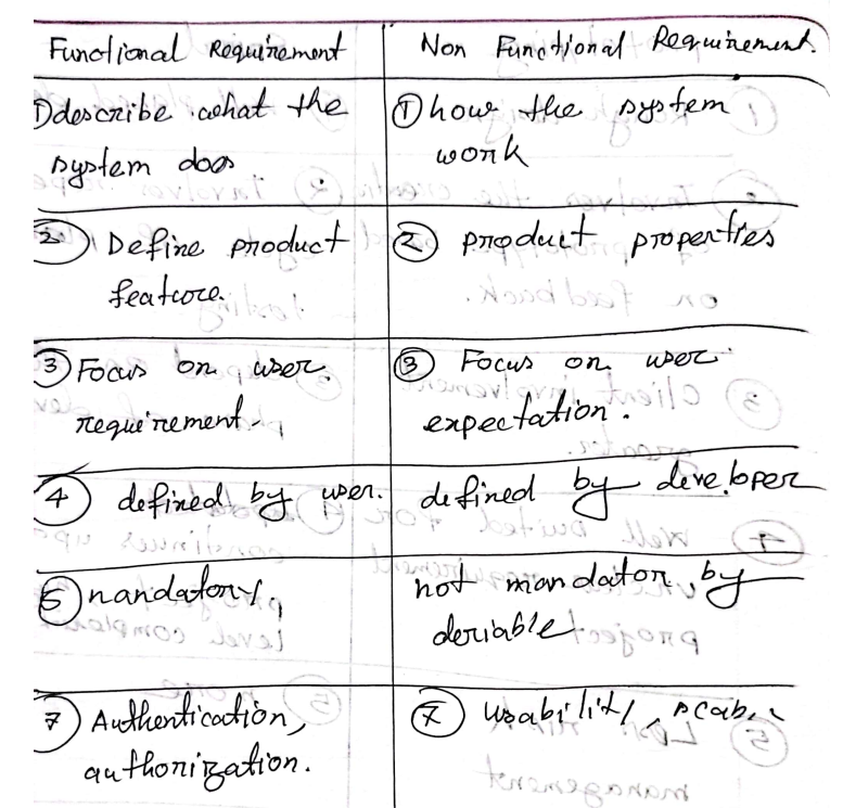
✅ Functional Requirements
🔹 Definition:
Functional requirements describe how the system should behave under specific conditions. They define features, actions, and rules that the system must implement.
🔹 Key Characteristics:
- Must be precise and clear for both developers and stakeholders.
- Describe what the system should do.
- Often documented using use cases.
🔹 Examples of Functional Requirements:
- Business rules
- Transaction corrections, adjustments, cancellations
- Administrative functions
- Authentication
- Authorization levels
- Audit tracking
- Reporting requirements
- External interfaces
- Certification requirements
- Historical data
✅ Non-Functional Requirements (NFRs)
🔹 Definition:
Non-functional requirements define the quality attributes of a system. They focus on how well the system performs, rather than what it does.
🔹 Key Characteristics:
- Define system standards, constraints, and qualities.
- Used to evaluate system performance, usability, and reliability.
🔹 Examples of Non-Functional Requirements:
| Category | Examples |
|---|---|
| Performance | Response time, throughput, resource utilization |
| Capacity | Data volume the system must handle |
| Availability | Uptime percentage or hours |
| Reliability | Frequency of failure or errors |
| Recoverability | Ability to restore from failures |
| Maintainability | Ease of making updates |
| Serviceability | Ease of system support |
| Security | Data protection and access control |
| Regulatory | Legal or industry compliance |
| Manageability | Ease of system monitoring and management |
| Environmental | Constraints based on the operating environment |
| Data Integrity | Accuracy and consistency of stored data |
| Usability | User-friendliness and interface design |
Elements of the Analysis Model
🔹 1. Scenario-Based Elements
| Type | Explanation |
| Functional | Narratives describing software functions |
| Use-Case | Interactions between an actor and the system |
🔹 2. Class-Based Elements
- Extracted from the scenarios
- Define data and objects within the system
🔹 3. Behavioral Elements
- Describe how the system behaves dynamically
- Example: State diagrams
🔹 4. Flow-Oriented Elements
- Represent the flow of data
- Example: Data Flow Diagrams (DFDs)
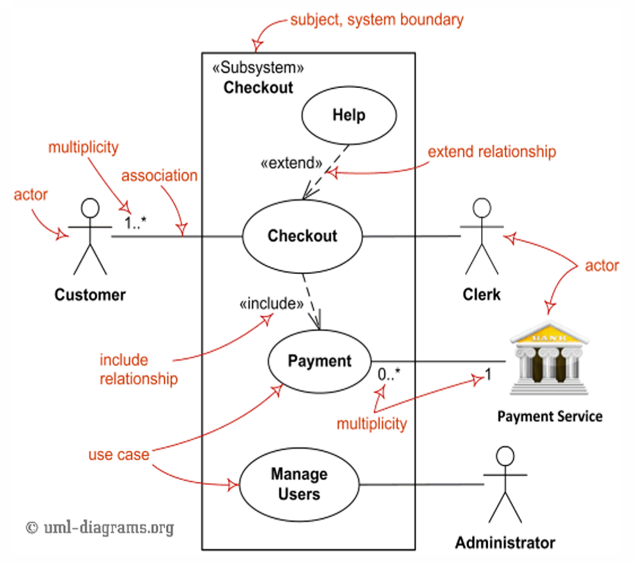
Use Cases
🔹 Definition:
A use case describes the interaction between a user (actor) and the system to achieve a specific goal.
🔹 Main Components:
| Element | Description |
| Actors | Users or systems that interact with the system. They can be primary or secondary. |
| System | Behaviors/functions the system must support. |
| Goals | The purpose of the interaction (what the actor wants to achieve). |
🔹 Actor Types:
| Actor Type | Role |
| Primary | Initiates the use case, interacts directly with the system (left side of the diagram). |
| Secondary | Supports the system, used by the system but doesn’t initiate interaction (right side of the diagram). |
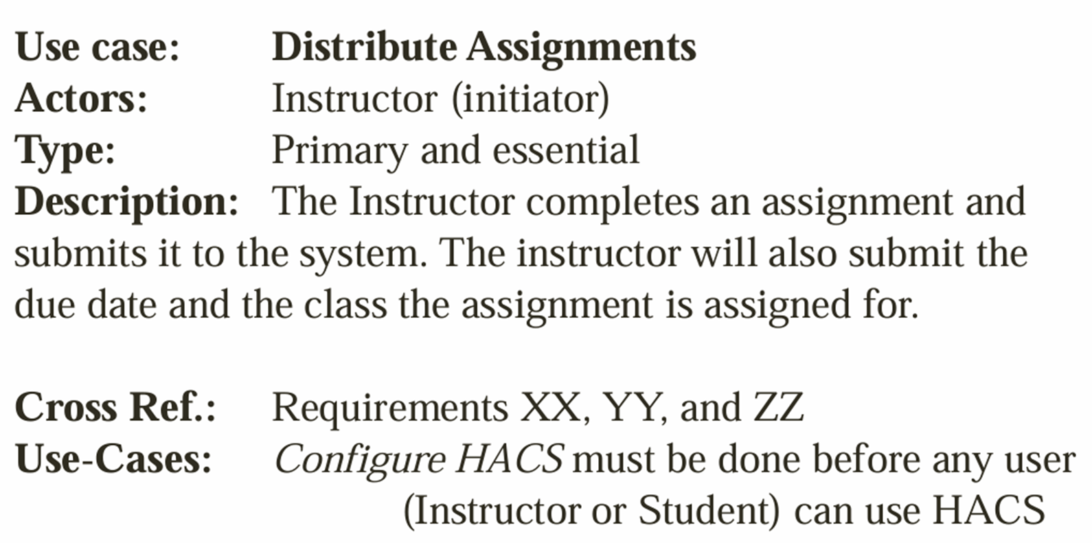
🔹 Representation Formats:
- Use Case Specification (text-based description of steps, actors, outcomes)
- Use Case Diagram (visual representation using UML notation)
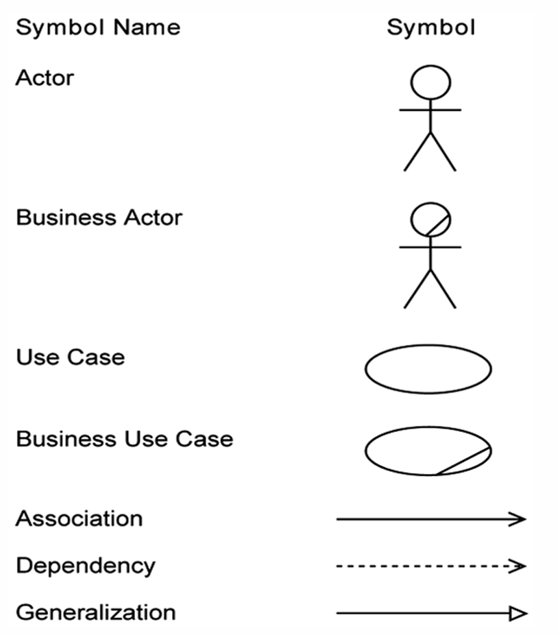
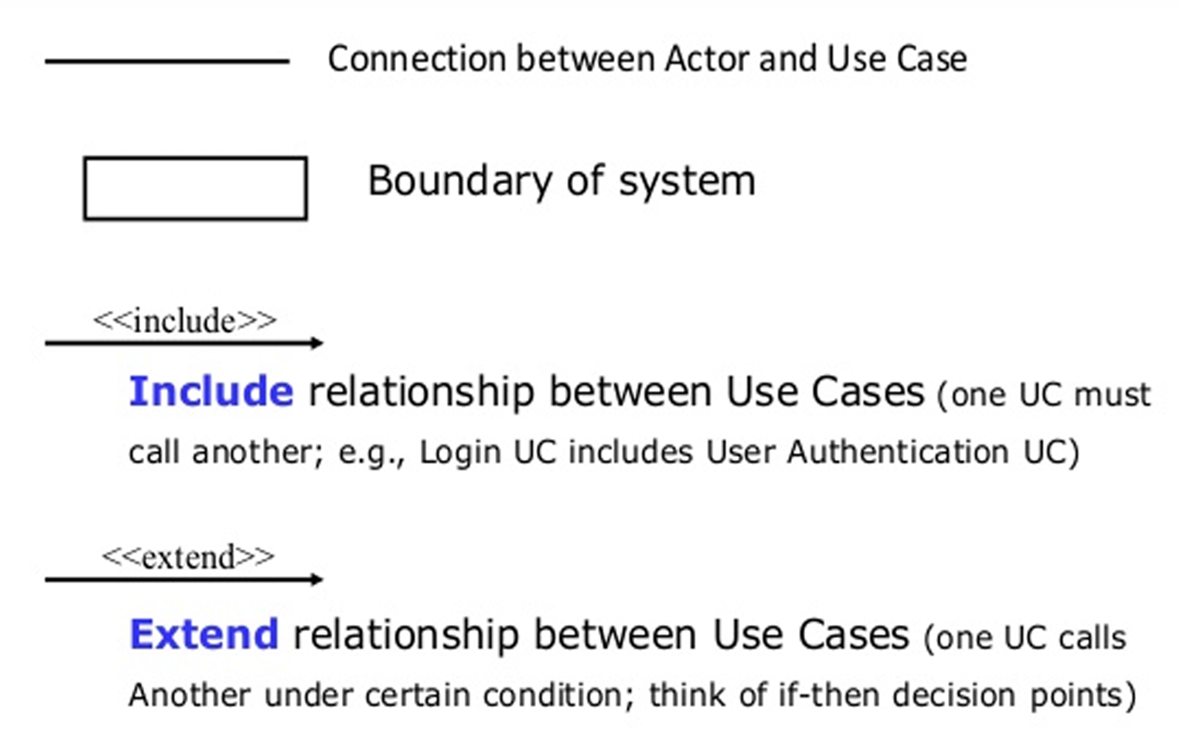
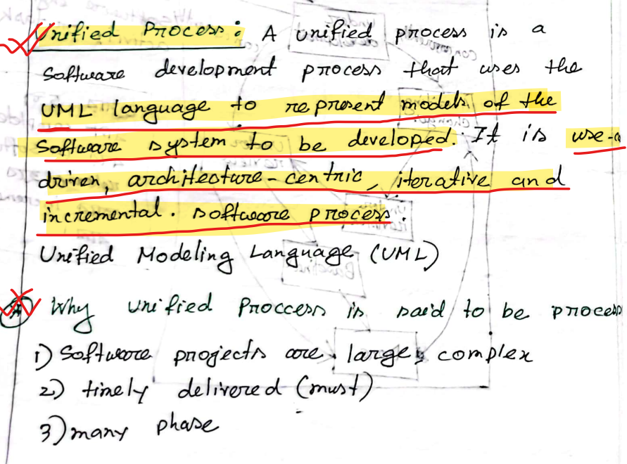
The Unified Modeling Language (UML) is a standardized visual modeling language used in software engineering to specify, visualize, construct, and document the artifacts of a software system.
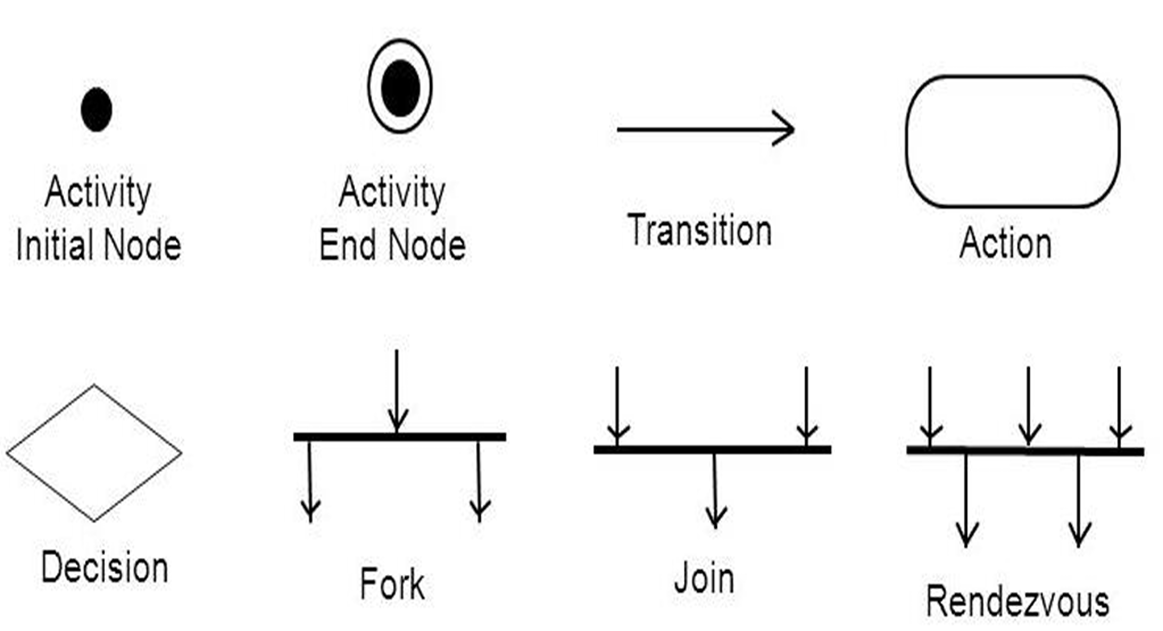
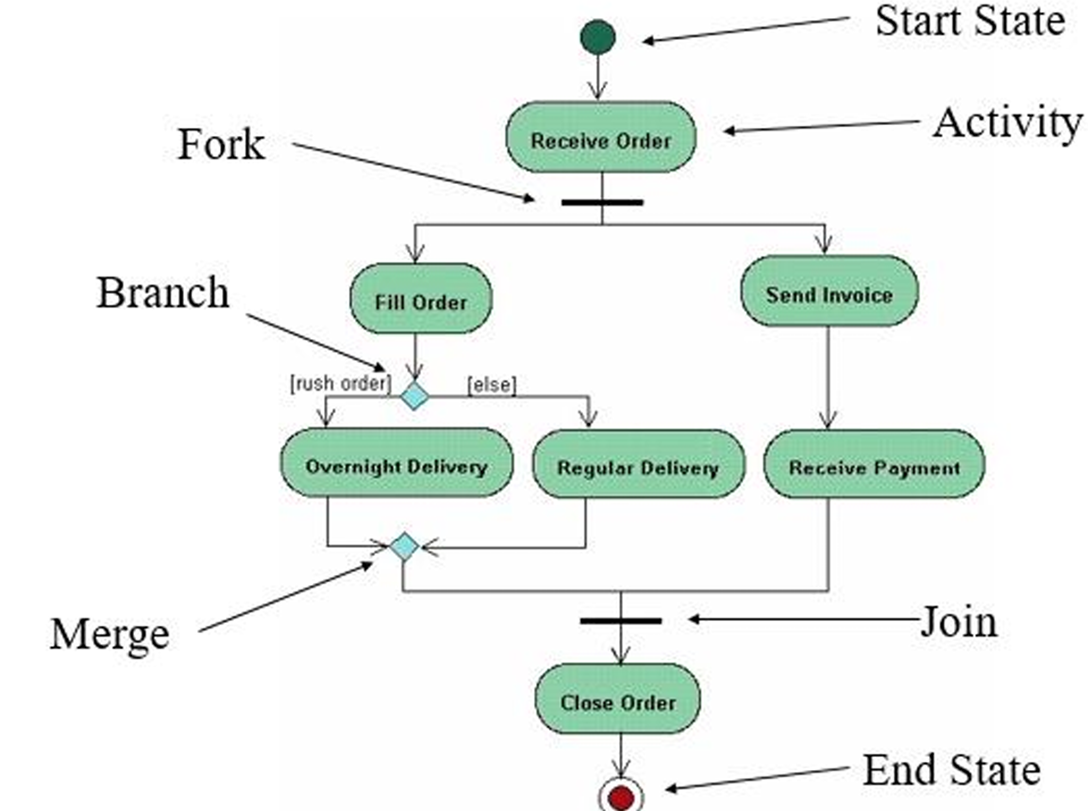
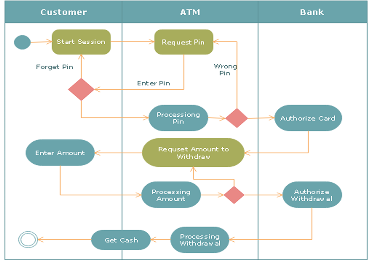
1. Activity Diagram
Definition: An activity diagram is a type of UML diagram that illustrates the dynamic aspects of a system by showing the workflow of control from one activity to another. It emphasizes the sequence and conditions for coordinating lower-level behaviors.
- Activity Diagrams to illustrate the flow of control in a system and refer to the steps involved in the execution of a use case.
Purpose: To model the flow of control in a system, often used to describe the steps in the execution of a use case.
Key Points:
- Represents parallel and conditional paths.
- Focuses on flow conditions and transitions.
- Useful for modeling business processes and workflows.
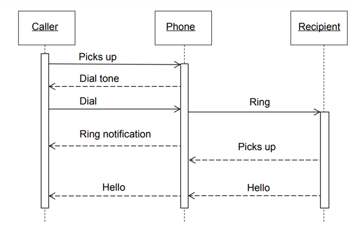
2. Sequence Diagram
Definition: A sequence diagram describes the interaction between objects in a sequential order. It shows how objects communicate with each other through messages over time.
Purpose: To represent how different parts of the system interact in a particular scenario.
Key Components:
- Lifelines: Vertical dashed lines that represent an object's presence over time.
- Messages: Horizontal arrows that show the communication between objects.
Use:
- To describe real-time specification and usage scenarios.
- To model the logic of a complex operation or workflow.
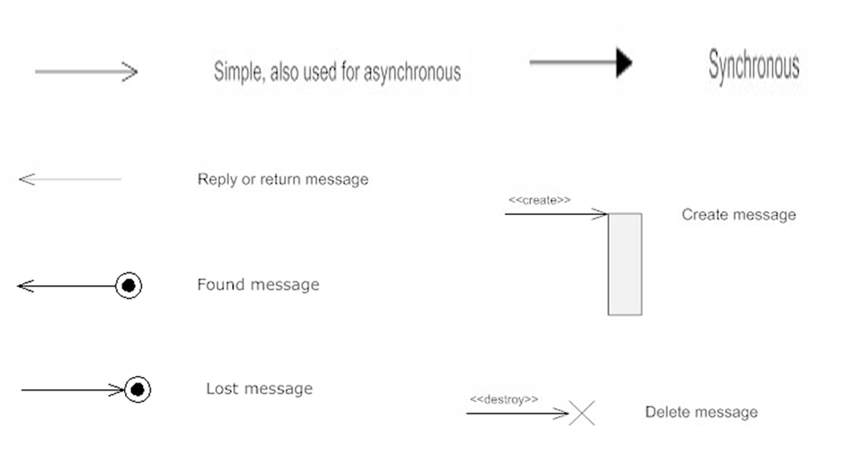
Types of message
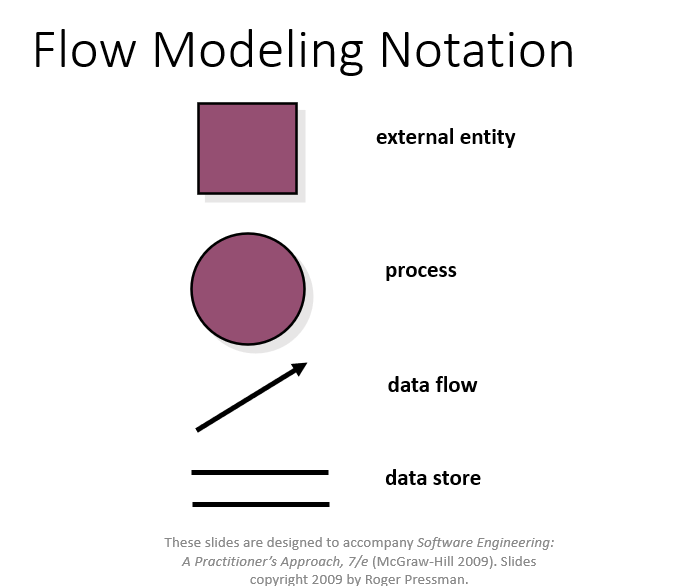
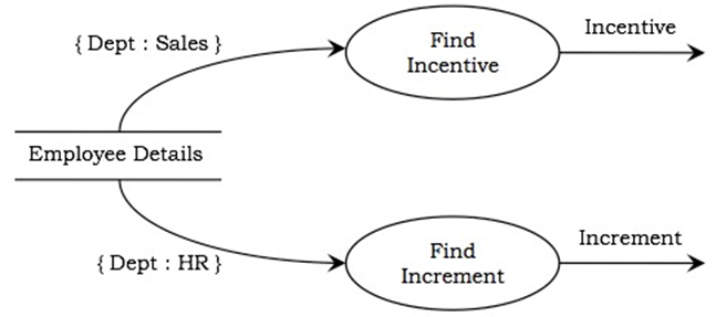
3. Data Flow Diagram (DFD)
Definition: A DFD is a graphical representation that illustrates the flow of data through a system. It depicts how input is turned into output through a sequence of transformations.
Main Parts:
- External Entity (Actor): Source or sink of data (represented by rectangles): Actors are the active objects that interact with the system by either producing data and inputting them to the system, or consuming data produced by the system. In other words, actors serve as the sources and the sinks of data.
- Process: Transformation of data (represented by ellipses) : Processes are the computational activities that transform data values. A whole system can be visualized as a high-level process. A process may be further divided into smaller components. The lowest-level process may be a simple function.
- Data Flow: Movement of data (represented by arrows): Data flow represents the flow of data between two processes. It could be between an actor and a process, or between a data store and a process. A data flow denotes the value of a data item at some point of the computation. This value is not changed by the data flow.
- Data Store: Storage for data (represented by parallel lines): Data stores are the passive objects that act as a repository of data. Unlike actors, they cannot perform any operations. They are used to store data and retrieve the stored data. They represent a data structure, a disk file, or a table in a database.
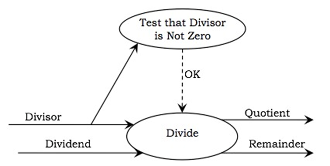
Supporting Elements:
- Constraints: Conditions that must hold true during data processing (represented by braces {}).
- Control Flows: Boolean values controlling the activation of processes (represented by dotted arrows). A process may be associated with a certain Boolean value and is evaluated only if the value is true,
4. Data Dictionary
Definition: A data dictionary is a centralized repository that contains metadata about the data (i.e database) in the system, including definitions, relationships, sources, usage, and formats.
- A data dictionary contains metadata i.e., data about the database.
- It plays an important role in building a database.
Purpose: To standardize definitions and facilitate consistency and communication among stakeholders.
The data dictionary in general contains information about the following:
- Names of tables and fields in the database
- Constraints on tables in the database
- Physical storage and access methods.
Advantages:
- Provides well-structured database documentation.
- Helps identify redundancy.
- Aids database administrators in management and maintenance.
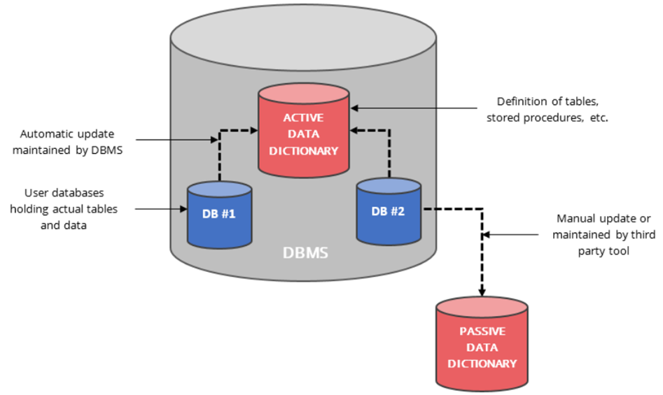
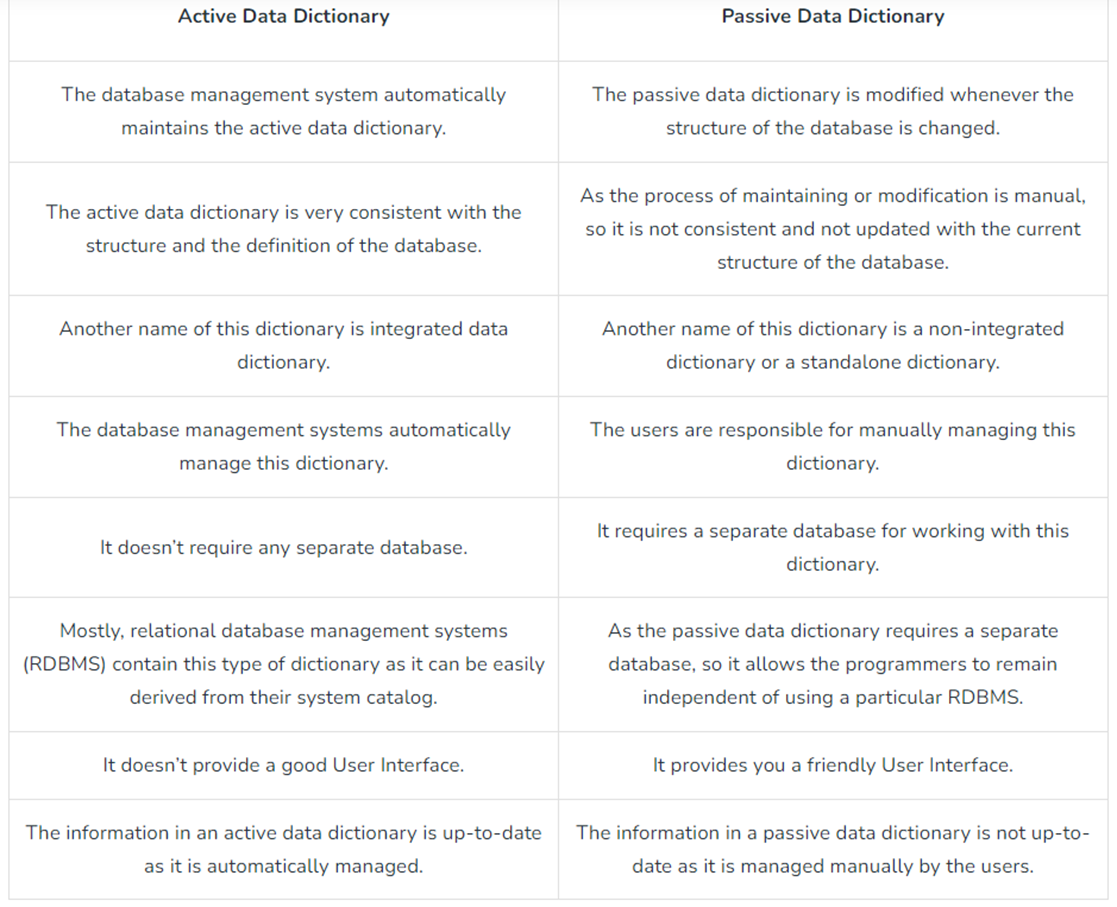
Types:
- Active Data Dictionary:
- An active data dictionary is a type of dictionary that is very consistent and managed automatically by the DBMS.
- Automatically updated by the DBMS.
- Changes in the database are reflected immediately.
- No external maintenance required.
- Cost-efficient and consistent.
- Passive Data Dictionary:
- Maintained manually or through external tools.
- High maintenance cost.
- Prone to becoming outdated.
- Difficult to manage, less reliable than active types.
Four Categories of Data Dictionary:
- Data Flows: Collection of data elements. Data flow is a collection of data elements
- Data Structures: Groups of elements. Usually algebraic notations
- Data Elements: Basic unit of data with specific definition. Data elements definitions describe a data type.
- Data Stores: Data stores are created for each different data entity being stored.
✅ 1. Class Model
A class model is a conceptual representation that describes the structure and behavior of objects within a software system. It defines:
- the objects to be manipulated,
- the attributes and operations associated with them,
- the relationships among these objects,
- and the collaborations that take place between the classes.
✅ 2. Data Modeling
Data modeling is the process of analyzing data objects without considering the processes acting upon them. It focuses on:
- independent data objects,
- their structure and characteristics,
- the relationships among them,
- and the customer's level of abstraction.
It creates a conceptual view of data that reflects how the end-users perceive it.
✅ 3. Data Object
A data object is a representation of any composite information required by the software. It can be:
- an external entity (e.g., user, sensor),
- a thing (e.g., report, document),
- an event (e.g., alarm),
- a role (e.g., administrator),
- a location (e.g., warehouse),
- or a structure (e.g., file or table).
A data object only encapsulates data — it does not define operations or behaviors.
✅ 4. Attributes
Attributes are descriptors or properties that define the characteristics of a data object.
Example:
- Object:
Automobile
- Attributes:
make,model,price,bodyType,color
✅ 5. Relationship
A relationship represents the connection between two or more data objects. It describes how objects are associated or interact with one another.
Example:
- A person owns a car.
- A person is insured to drive a car.
✅ 6. ERD (Entity Relationship Diagram)
An ERD is a graphical notation used to illustrate data objects (entities), their attributes, and the relationships between them. It includes:
- Entity symbols
- Relationship connectors
- Cardinality/multiplicity indicators such as:
- (1,1) → exactly one
- (0,m) → zero or more
✅ 7. Class-Based Modeling
Class-based modeling represents:
- Objects that the system will use or manage
- Operations that act on those objects
- Relationships (including inheritance or aggregation)
- Collaborations between different classes
Key elements include:
- Classes, attributes, operations
- CRC models
- Collaboration diagrams
- Packages
✅ 8. Identifying Analysis Classes
To identify candidate classes from requirements:
- Perform a grammatical parse of scenarios (underline all nouns)
- Each noun may represent a potential class
- Determine whether the noun belongs to:
- Solution space (used in implementation)
- Problem space (used in description only)
✅ 9. Manifestations of Analysis Classes
Analysis classes may take the form of:
| Type | Example |
| External Entities | Users, hardware devices |
| Things | Reports, signals, documents |
| Occurrences/Events | Transactions, triggers |
| Roles | Manager, customer, admin |
| Organizational Units | Department, team |
| Places | Factory floor, loading dock |
| Structures | Sensor, vehicle, table |
✅ 10. Criteria for Potential Classes
| Criterion | Description |
| Retained Information | The class must retain data necessary for system operation |
| Needed Services | It must support relevant operations (methods) |
| Multiple Attributes | Must have more than one meaningful attribute |
| Common Attributes | All instances share the same set of attributes |
| Common Operations | Similar operations applicable to all instances |
| Essential Requirements | Essential for communication between system and external entities |
✅ 11. Defining Attributes
Attributes are assigned depending on the context of the class in the system.
Example:
- For a Sports Management System:
name,battingAverage,fieldingPercentage
- For a Pension System:
salary,pensionOption,vestingStatus
✅ 12. Defining Operations
Operations represent the behavior of a class. They are identified by parsing verbs from the requirements.
Four Categories:
- Data Manipulation (add, update, delete)
- Computation (calculate salary, total marks)
- Inquiry (check status)
- Event Monitoring (detect threshold breach, motion detection)
✅ 13. CRC Models (Class-Responsibility-Collaborator)
CRC (Class-Responsibility-Collaborator) modeling uses index cards to document:
- Class name
- Responsibilities (left side)
- Collaborators (right side)
This method helps visualize how classes interact and what responsibilities they carry.
✅ 14. Class Types
| Type | Purpose |
| Entity Class | Represents core domain concepts (e.g., Sensor, FloorPlan) |
| Boundary Class | Manages user interface (e.g., forms, reports) |
| Controller Class | Coordinates operations, workflows, and communication between classes |
✅ 15. Responsibilities
- Distribute responsibilities logically among classes
- Keep related data and behavior together
- Avoid scattering related data across multiple classes
- Responsibilities should be general and reusable
- Shared where needed across related classes
✅ 16. Collaborations
Classes fulfill their responsibilities either:
- Independently (using their own methods)
- Collaboratively (interacting with other classes)
Types of relationships:
- Is-part-of
- Has-knowledge-of
- Depends-upon
✅ 17. Associations and Dependencies
| Term | Explanation |
| Association | A structural relationship (e.g., student enrolls in courses) |
| Dependency | A situation where one class relies on another to perform a task or supply data |
✅ 18. Multiplicity
Specifies the number of instances that can be involved in a relationship:
- (1,1) → Exactly one
- (0,m) → Zero or many
- (1,n) → At least one
✅ 19. Analysis Packages
To organize a large model, related classes and use-cases are grouped into packages.
Visibility symbols:
+→ Public (accessible everywhere)
- → Private (not accessible outside the package)
#→ Protected (accessible only to related packages)
Project Planning
Project Planning is an organized process from requirements gathering to testing and support.
Software Project Manager
Managing People
- Act as a Project Leader
- Contact with stakeholders
- Managing human resources
Managing Projects
- Defining and setting up project scope
- Managing project management activities
- Monitoring progress and performance
- Risk analysis
- Take necessary step to avoid or come out of problems
Project Planning Process
- Identify Stakeholders Need: meet the expectations of stakeholders
- Identify Project Objectives: specific, measurable, achievable objectives
- Deliverable and due dates: fixed date and time that an objective is due, deliverables = products, service or result
- Project Schedules: project start and end date
- Provide Roles and Responsibilities: effective communication, who is involved and their task, understand expected objective
- Identify Project budget: anticipating budget cost, monitoring budget
- Identify Communication Plan: effective communicate with client, team and others
- Provide tracking and management: deliver project on time and organize task, track productivity and growth of project
Resource used in Project Management
- Human
- Reusable Components
- Hardware and Software tools
Project Scope Management
Scope = set of deliverables or features of a project
Scope management = creates boundaries of the project by clearly defining what would be done and what not
Steps
- Plan Scope Managements : documentarian and guidelines of project scope, product scope, project life, how to define, validate and control.
- Collect Requirements: collect requirements from all stakeholders
- Defining Scope: identifying project objectives, goals, tasks, budget, resources, schedule, expectation
- Create WBS: Work Breakdown Structure = subdividing project deliverables into smaller units, break down into phases, including priority task
- Validate Scope: focuses on mainly customer acceptance, customer gives feedback
- Control Scope: monitoring the status of the project and managing changes
WBS : Work Breakdown Structure
A top-down hierarchical decomposition of the total project scope into manageable sections.
Working of WBS Steps
- Project managers decide project name at top
- Project managers identifies the main deliverables of the project
- These main deliverables are broke down into smaller higher-level tasks
- Process is done recursively to produce much smaller independent task
- Choose task owner. they need to get the job down
Components
- WBS Dictionary: Document that defines the various wbs element
- WBS levels: determines the hierarchy level of a wbs elemet
- Task : main deliverable tasks
- Sub tasks: devided tasks
- Control account : group work packages and measure their status
- project deliverables: desired outcome of project tasks and work package
Project Scheduling
Definition: The process of converting a project plan into an operating timetable.
Project scheduling is responsible activity of project manager.
Process:
- Identify all the functins required
- \Break down large function into smaller activites , wbs
- Determine the dependency among various activities
- Allocate resources to activities
- Assign people to conduct different activities
- Plan the beginning and ending dates for different activities
- Create activity network and bar or gratt chart
Techniques:
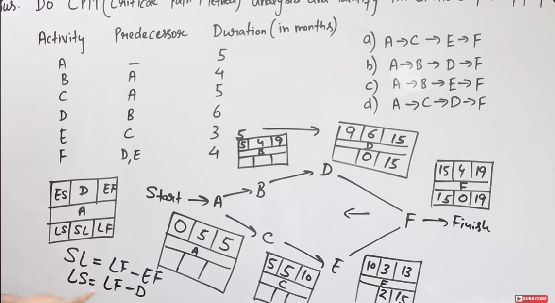
- CPM :
The Critical Path Method (CPM), also known as Critical Path Analysis (CPA), is a project management technique that identifies the longest sequence of tasks (the critical path) that must be completed on time to finish the project, highlighting tasks that directly impact the project's timeline.
Lecture 10: Risk Management in Software Projects
Introduction
Risk management is a critical component of software project planning, aimed at identifying, analyzing, and controlling risks to ensure project success. A risk is an uncertain future event with a probability of occurrence and potential for loss, impacting time, budget, performance, or project outcomes.
Sources of Risk
Risks in software projects arise from various sources, including:
- Misunderstanding Customer Requirements: Incorrect or unclear interpretation of client needs.
- Uncontrolled Requirement Changes: Frequent or poorly managed changes to requirements.
- Unrealistic Promises: Overcommitting to clients beyond project capabilities.
- Misjudging New Methodologies: Overestimating the benefits or underestimating the challenges of new tools or processes.
- Poor Software Design: Underestimating the robustness or extensibility of the design.
- Team Effectiveness Miscalculation: Overestimating team collaboration or productivity.
- Inaccurate Budget Estimation: Underestimating costs or resources needed.
Risk Identification
Risk identification involves detecting potential risks early to minimize their impact. Techniques include:
- Brainstorming: Collaborative sessions to identify potential risks.
- SWOT Analysis: Evaluating strengths, weaknesses, opportunities, and threats.
- Causal Mapping: Mapping cause-and-effect relationships to uncover risks.
- Flowcharting: Visualizing processes to identify risk points.
Types of Risks
- Technology Risks: Issues with hardware or software used in development.
- People Risks: Challenges related to team members, such as turnover or skill gaps.
- Organizational Risks: Problems stemming from the organizational environment.
- Tools Risks: Issues with development tools or support software.
- Requirement Risks: Risks from changing or mismanaged customer requirements.
- Estimation Risks: Errors in estimating resources, time, or costs.
Risk Analysis and Prioritization
Risk analysis assesses identified risks by:
- Identifying Problems: Determining the root causes of risks.
- Estimating Probability: Calculating the likelihood of occurrence.
- Assessing Impact: Evaluating the potential effect on the project.
Probability Categories
- Very Low (0–10%): Tolerable risk with no significant harm.
- Low (10–25%): Minor effect on the project.
- Moderate (25–50%): Impacts project timeline.
- High (50–75%): Affects timeline and budget.
- Very High (>75%): Severe impact on output, time, budget, and performance.
Risk Control
Risk control involves planning, monitoring, and resolving risks to achieve desired project outcomes.
1. Risk Planning
Risk planning develops strategies to mitigate significant risks. Methods include:
- Avoid the Risk: Modify requirements, reduce scope, or offer incentives to retain staff.
- Transfer the Risk: Outsource risky components or purchase insurance.
- Reduce the Risk: Plan for potential losses, such as recruiting additional staff to cover turnover.
2. Risk Monitoring
Risk monitoring is an ongoing process to track project progress and evaluate risks:
- Continuously assess assumptions about risks.
- Identify changes in risk probability or impact.
- Take corrective actions as needed to keep risks under control.
3. Risk Resolution
Risk resolution ensures risks are managed within acceptable levels:
- Depends on accurate risk identification, analysis, and planning.
- Requires prompt and effective responses to emerging issues.
- Keeps the project on track by addressing risks as they arise.
RMMM Plan
The Risk Mitigation, Monitoring, and Management (RMMM) Plan is a structured approach integrated into the overall project plan. It documents risks using a Risk Information Sheet (RIS), which includes:
- Risk ID, date, probability, impact, description, avoidance strategies, monitoring actions, management plan, and current status.
- Managed via a database for easy creation, prioritization, searching, and analysis.
Example: Late Project Delivery
Risk: Project delivery exceeds the deadline.
- Mitigation:
- Estimate development time as 20 days but quote 30 days to the client for buffer.
- Implement precautionary measures before development starts.
- Monitoring:
- Create a project schedule with clear start and end dates.
- Track progress within the 20–30-day window.
- Management:
- If the deadline is missed, negotiate with the client for extra time or offer additional features to maintain satisfaction.
Risk Mitigation
Risk mitigation is a proactive approach to avoid risks before they occur. Steps include:
- Communicate with staff to identify potential risks.
- Eliminate causes of risks (e.g., unclear requirements).
- Develop policies to ensure project continuity.
- Regularly review and control project documents.
- Conduct timely reviews to accelerate progress.
Risk Management
Risk management is a reactive approach applied after risks materialize:
- Assumes mitigation efforts failed, and the risk has occurred.
- Handled by the project manager to resolve issues.
- Effective mitigation simplifies management (e.g., sufficient staff, clear documentation, and shared knowledge ease onboarding of new team members).
Example Scenario
Risk: High staff turnover.
- Mitigation Success: Sufficient additional staff, comprehensive documentation, and shared knowledge ensure new employees can quickly adapt.
- Management: Project manager leverages these resources to maintain development continuity.
Drawbacks of RMMM
While effective, the RMMM approach has limitations:
- Additional Costs: Implementing RMMM increases project expenses.
- Time-Intensive: Requires significant time for planning and execution.
- Complex for Large Projects: RMMM can become a project in itself.
- No Guarantee: Risks may still emerge post-delivery, and RMMM does not ensure a risk-free project.
Conclusion
Effective risk management in software projects involves identifying, analyzing, and controlling risks through proactive mitigation and reactive management. The RMMM Plan provides a structured framework to document and address risks, but it requires careful planning and resources. By understanding risk sources, types, and control strategies, project managers can enhance the likelihood of successful project outcomes.
Lecture 11 : Design Concepts
Introduction
Software design is the process of transforming user requirements into a form suitable for coding and implementation. As the first step in the Software Development Life Cycle (SDLC), it shifts focus from the problem domain to the solution domain, specifying how to fulfill requirements outlined in the Software Requirements Specification (SRS). Software design is typically performed by software design engineers or UI/UX designers.
Mitch Kapor’s Software Design Manifesto
Mitch Kapor, creator of Lotus 1-2-3, emphasized three qualities of good software design:
- Firmness: The software should be free of bugs that impair functionality.
- Commodity: The software should meet its intended purpose.
- Delight: The user experience should be pleasurable.
Objectives of Software Design
A well-designed software system should achieve:
- Correctness: Accurately meet the specified requirements.
- Completeness: Include all necessary components, such as data structures, modules, and interfaces.
- Efficiency: Optimize resource usage.
- Flexibility: Adapt to changing needs.
- Consistency: Maintain uniformity across the design.
- Maintainability: Be simple enough for other designers to maintain.
Software Quality Attributes (FURPS)
The FURPS model defines key quality attributes for software design:
- Functionality: Evaluates the feature set, capabilities, generality of functions, and system security.
- Usability: Considers human factors, aesthetics, consistency, and documentation.
- Reliability: Measures failure frequency, output accuracy, mean-time-to-failure (MTTF), recovery ability, and predictability.
- Performance: Assesses processing speed, response time, resource consumption, throughput, and efficiency.
- Supportability: Encompasses extensibility, adaptability, serviceability, testability, compatibility, configurability, ease of installation, and problem localization (collectively contributing to maintainability).
Software Quality Guidelines
To ensure high-quality design, the following guidelines should be followed:
- Use recognizable architectural styles or patterns and components with good design characteristics.
- Enable evolutionary implementation, allowing incremental development (though smaller systems may use linear design).
- Ensure modularity by logically partitioning software into elements or subsystems.
- Provide distinct representations of data, architecture, interfaces, and components.
- Select data structures based on recognizable patterns suitable for implementation.
- Design components with independent functional characteristics.
- Create interfaces that reduce complexity between components and external systems.
- Derive the design using a repeatable method driven by requirements analysis.
- Represent the design with notation that clearly communicates its meaning.
Software Design Process
The software design process translates the analysis model (requirements) into a design model (solution) and consists of three levels:
- Interface Design:
- Focuses on interactions between the system and users/devices.
- Uses scenario-based and behavioral diagrams (e.g., use case diagrams).
- Does not address internal structure.
- Architectural Design:
- Defines major system components, their responsibilities, properties, interfaces, and interactions.
- Uses class-based and flow-based diagrams (e.g., class diagrams, data flow diagrams).
- Detailed Design:
- Specifies internal elements of major components, including properties, relationships, processing, algorithms, and data structures.
The design must:
- Implement all explicit and implicit requirements from the analysis model.
- Be a readable, understandable guide for coders, testers, and support teams.
- Provide a complete picture of the software, addressing data, functional, and behavioral domains from an implementation perspective.
Fundamental Design Concepts
Software design concepts provide the principles and logic behind creating effective software designs. These concepts form a supporting structure for development.
1. Abstraction
Abstraction hides unnecessary implementation details, showing only essential information to users.
- Procedural Abstraction: Divides subprograms into hidden and visible groups of functionalities (e.g., a function like open() hides the details of the enter algorithm).
- Data Abstraction: Represents data objects while hiding manipulation details (e.g., a stack’s Push(), Pop(), Top(), and Empty() methods hide internal data structure implementation).
- Example: A door object might expose attributes like manufacturer, model, type, and swing direction while hiding internal data structures.
2. Architecture
Architecture defines the overall structure of program modules and their interactions, providing conceptual integrity.
- Structural Properties: Defines components (e.g., modules, objects) and their interactions (e.g., method invocations).
- Extra-Functional Properties: Addresses performance, capacity, reliability, security, and adaptability requirements.
- Families of Systems: Leverages reusable architectural patterns for similar systems.
- Reference: Shaw and Garlan [SHA95a].
3. Design Patterns
Design patterns are reusable solutions to common design problems.
- Pattern Template:
- Name: A concise, expressive name.
- Intent: Describes the pattern’s purpose.
- Also-Known-As: Lists synonyms.
- Motivation: Provides a problem example.
- Applicability: Specifies relevant design situations.
- Structure: Describes required classes.
- Participants: Outlines class responsibilities.
- Collaborations: Details participant interactions.
- Consequences: Discusses trade-offs and design forces.
- Related Patterns: References related patterns.
4. Separation of Concerns
Separation of concerns divides complex problems into smaller, independently solvable pieces.
- Each concern represents a feature or behavior from the requirements model.
- Reduces effort and time by making problems more manageable.
5. Modularity
Modularity divides a system into smaller, manageable parts (modules) to reduce complexity.
- Modules are integrated to meet software requirements.
- Benefits: Makes software intellectually manageable, reduces development costs, and improves understanding [Mye78].
- Contrast: Monolithic software (single module) is difficult to understand due to numerous control paths, variables, and complexity.
6. Information Hiding
Information hiding ensures modules only share necessary information, hiding internal data structures and algorithms.
- Benefits:
- Reduces side effects.
- Limits the global impact of local design decisions.
- Encourages controlled interfaces.
- Discourages global data usage.
- Promotes encapsulation, enhancing design quality.
7. Functional Independence
Functional independence is achieved through modules with single-minded functions and minimal interaction (low coupling, high cohesion).
- Cohesion: The degree to which a module performs a single task with little interaction with others (high cohesion is desirable).
- Coupling: The degree of interdependence between modules (low coupling is desirable).
- Benefits of High Cohesion and Low Coupling:
- Readability: Modules are easier to understand.
- Maintainability: Changes in one module have minimal impact on others.
- Modularity: Simplifies module development.
- Scalability: Facilitates adding or removing modules.
- Testability: Simplifies testing and debugging.
- Reusability: Modules can be reused in other systems.
- Reliability: Improves overall system quality.
8. Refinement
Refinement is a top-down approach that elaborates procedural details hierarchically until programming language statements are reached.
- Example: The task “open door” is refined into steps like “walk to door,” “reach for knob,” “turn knob clockwise,” and so on, until all details are specified.
9. Aspects
Aspects represent cross-cutting concerns—requirements that affect multiple parts of the design.
- Definition: Requirement A cross-cuts requirement B if B cannot be satisfied without considering A [Ros04].
- Example: In the SafeHomeAssured.com WebApp:
- Requirement A: Access camera surveillance via the internet.
- Requirement B: Validate registered users before access.
- B cross-cuts A because user validation (B) must be implemented across all functions, including camera access (A).
10. Refactoring
Refactoring improves a software system’s internal structure without altering its external behavior [FOW99].
- Purpose: Eliminates redundancy, unused elements, inefficient algorithms, or inappropriate data structures to enhance design quality.
Object-Oriented (OO) Design Concepts
OO design leverages principles to create flexible, reusable designs:
- Design Classes:
- Entity Classes: Refined from analysis classes to represent data and behavior.
- Boundary Classes: Manage user interfaces (e.g., screens, reports) and represent entity objects to users.
- Controller Classes: Handle creation/update of entity objects, instantiation of boundary objects, complex communication, and data validation.
- Inheritance: Subclasses inherit all responsibilities of their superclass.
- Messages: Stimulate behavior in receiving objects.
- Polymorphism: Allows objects to be treated as instances of their parent class, reducing effort to extend designs.
Design Model Elements
The design model transforms the analysis model into a detailed implementation plan, encompassing:
- Data Elements:
- Data structures derived from the data model.
- Database architecture for persistent storage.
- Architectural Elements:
- Derived from the application domain, analysis classes, and architectural patterns/styles [Sha96].
- Define relationships, collaborations, and behaviors for design realizations.
- Interface Elements:
- User interfaces (UI).
- External interfaces to other systems, devices, or networks.
- Internal interfaces between design components.
- Component Elements:
- Detailed specifications of software components, including algorithms and processing logic.
- Deployment Elements:
- Define how software components are deployed across hardware or network environments.
Conclusion
Software design bridges user requirements and implementation, ensuring correctness, efficiency, and maintainability. By adhering to quality guidelines, leveraging fundamental concepts (e.g., abstraction, modularity, functional independence), and applying OO principles, designers create robust, scalable systems. The design process—interface, architectural, and detailed design—transforms analysis models into actionable plans, supported by a comprehensive design model.
Reference
Pressman, R. S. (2010). Software Engineering: A Practitioner’s Approach, 7th Edition. McGraw-Hill.
Lecture 11: Software Project Management and Scheduling
Introduction
Software project management involves planning, organizing, and controlling resources to deliver a software product that meets customer requirements within time and budget constraints. Effective project management focuses on scheduling, cost estimation, and risk management to ensure project success. This guide covers key concepts, techniques, and models for managing and scheduling software projects, optimized for exam preparation.
Project Management Spectrum
Effective software project management revolves around four key components, known as the Four P’s:
1. People
- Importance: Human resources are the most critical factor in project success.
- Selection: Choose individuals with the right skills and talents.
- Roles and Responsibilities:
- Senior Manager: Defines business issues and influences the project.
- Project Manager: Plans, motivates, organizes, and controls project activities; possesses problem-solving and team management skills.
- Software Engineer: Delivers technical expertise.
- Customer: Specifies requirements.
- End Users: Interact with the final software product.
2. Product
- Definition: The software product is the ultimate deliverable of the project.
- Planning Requirements:
- Establish objectives and scope.
- Identify alternative solutions.
- Define technical and management constraints.
- Importance: Accurate product definition enables realistic cost estimation, risk identification, and scheduling.
3. Process
- Definition: A methodology that outlines steps to complete the project as per requirements.
- Importance: A clear process ensures team members know their tasks and timelines, increasing the likelihood of meeting project goals.
- Phases:
- Documentation
- Designing
- Implementation
- Software Configuration Management
- Deployment
- Interaction
4. Project
- Definition: Encompasses requirement analysis, development, delivery, maintenance, and updates.
- Project Manager’s Role:
- Guides the team to achieve objectives.
- Resolves issues, monitors costs, and ensures adherence to deadlines.
- Manages activities to prevent project failure.
Boehm’s W5HH Principle
Barry Boehm’s W5HH (Why, What, When, Who, Where, How, How Much) principle provides a framework for efficient project management by answering key questions:
- Why is the system being developed?
- Identifies business reasons and problem statements to justify the project’s cost and time.
- What activities are needed?
- Defines key tasks required by the customer to establish a project schedule.
- When will it be completed?
- Specifies start and end dates for tasks to meet project goals.
- Who is responsible for each activity?
- Assigns roles and responsibilities to team members.
- Where are they organizationally located?
- Clarifies that responsibilities may extend beyond the software team to customers, users, and stakeholders.
- How will the job be done technically and managerially?
- Defines technical and management strategies once the product scope is established.
- How much of each resource is needed?
- Estimates resources required to complete the project within budget and requirements.
Software Measurements and Metrics
Software measurements and metrics quantify attributes of the software product or process to aid decision-making and project success.
Software Measurements
- Definition: Indicators of size, quantity, or dimension of a product or process attribute.
- Categories:
- Direct Measures: Cost, effort, lines of code (LOC), execution speed, error count.
- Indirect Measures: Functionality, quality, complexity, reliability, maintainability.
Software Metrics
- Definition: Formulas or measures for software process and product aspects (e.g., performance, productivity).
- Categories:
- Product Metrics: Measure size, complexity, quality, and reliability.
- Process Metrics: Measure fault rates, testing defect patterns, and operation times.
- Project Metrics: Measure developer count, cost, scheduling, and productivity.
Principles of Software Measurement
- Formulation: Derive appropriate measures and metrics.
- Collection: Gather data to compute metrics.
- Analysis: Apply mathematical tools to compute metrics.
- Interpretation: Evaluate metrics to gain insights into quality.
- Feedback: Provide recommendations to the software team based on metric analysis.
Size Metrics
Size metrics estimate the software’s size, critical for cost and effort estimation.
1. Lines of Code (LOC)
- Definition: Counts executable code lines, excluding comments and blank lines.
- Use: Estimates program size and compares programmer productivity.
- Example:
//Import header file #include <iostream> int main() { int num = 10; //Logic of even number if (num % 2 == 0) { cout << "It is even number"; } return 0; }- Total LOC = 9 (executable lines only).
- Advantages:
- Widely used for cost estimation.
- Easy to estimate efforts.
- Disadvantages:
- Cannot measure specification size.
- Poor design may inflate LOC.
- Language-dependent.
- Difficult for users to understand.
- Example Table:
Project LOC Cost (SR) Efforts (Persons/Month) Documents Errors A 10,000 110 18 365 39 B 12,000 115 20 370 45 C 15,400 130 25 400 32
2. Function Points (FP)
- Definition: Measures functionality by counting functions in the application.
- Attributes:
- External Inputs (EI): Input screens, tables.
- External Outputs (EO): Output screens, reports.
- External Inquiries (EQ): Prompts, interrupts.
- Internal Logical Files (ILF): Databases, directories.
- External Interface Files (EIF): Shared databases, routines.
- Calculation:
- Count each attribute, assign weights, and compute Unadjusted Function Count (UFC).
- Apply Complexity Adjustment Factor (CAF) to get FP.
- Example:
Information Domain Optimistic Likely Pessimistic Est. Count Weight FP Count # of Inputs 22 26 30 26 4 104 # of Outputs 16 18 20 18 5 90 # of Inquiries 16 21 26 21 4 84 # of Files 4 5 6 5 10 50 # of External Interfaces 1 2 3 2 7 14 UFC 342 CAF 1.17 FP 400
- Advantages:
- Requires detailed specifications.
- Not restricted to code.
- Language-independent.
- Disadvantages:
- Ignores quality issues.
- Subjective counting relies on estimation.
Software Project Estimation
Software project estimation predicts the time, effort, and cost required to complete a project, critical for preventing project failure.
Responsible Persons
- Software Manager
- Cognizant Engineers
- Software Estimators
Factors Affecting Estimation
- Cost: Ensure sufficient funds to avoid project failure.
- Time: Estimate overall duration and task timings to manage client expectations.
- Size and Scope: Identify all tasks to ensure adequate materials and expertise.
- Risk: Predict potential events and their severity to create risk management plans.
- Resources: Ensure availability of tools, people, hardware, and software.
Steps of Project Estimation
- Estimate Project Size:
- Use LOC or FP, based on customer requirements, SRS, and system design documents.
- Methods: Estimation by analogy (past projects) or dividing the system into subsystems.
- Estimate Efforts:
- Calculate person-hours or person-months for activities (design, coding, testing, documentation).
- Methods:
- Use historical organizational data for similar projects.
- Apply algorithmic models (e.g., COCOMO) for unique projects.
- Estimate Project Schedule:
- Define the Work Breakdown Structure (WBS) to assign tasks, start/end dates, and team members.
- Convert efforts to calendar months using:Schedule (months) = 3.0 * (man-months)^(1/3)(The constant 3.0 varies by organization).
- Estimate Project Cost:
- Include labor costs (effort hours * labor rate) and other expenses (hardware, software, travel, training, office space).
- Use specific labor rates for different roles for accuracy.
Decomposition Techniques
Decomposition techniques break down the project into manageable parts for accurate estimation.
1. Software Sizing
- Challenge: Accurately estimate the product size.
- Factors for Accuracy:
- Correct size estimation.
- Translation of size into effort, time, and cost.
- Reflection of team abilities in the plan.
- Stability of requirements and environment.
- Approaches:
- Fuzzy Logic Sizing: Uses application type and historical data.
- Function Point Sizing: Estimates based on information domain characteristics.
- Standard Component Sizing: Estimates size of subsystems, modules, or screens using historical data.
- Change Sizing: Estimates modifications to existing software (reuse, add, change, delete code).
2. Problem-Based Estimation
- Method: Uses LOC or FP to size software elements and project costs/efforts.
- Steps:
- Size each element using LOC or FP.
- Use historical data to project costs and efforts.
- Compute expected value:S = (S_opt + 4S_m + S_pess) / 6(S = size, S_opt = optimistic, S_m = most likely, S_pess = pessimistic).
- Example:
Function Estimated LOC User Interface (UICF) 2,300 2D Geometric Analysis 5,300 3D Geometric Analysis 6,800 Database Management 3,350 Graphics Display 4,950 Peripheral Control 2,100 Design Analysis 8,400 Total 33,200
3. Process-Based Estimation
- Method: Decomposes the process into tasks and estimates effort for each.
- Steps:
- Identify software functions and process activities.
- Estimate effort (person-months) for each activity per function.
- Apply labor rates to calculate costs (senior staff may have higher rates).
- Importance: Ensures detailed task-level estimation for accuracy.
Software Cost Estimation
Software cost estimation predicts the approximate cost before development begins, considering multiple factors.
Factors for Project Budgeting
- Specification and scope
- Location
- Duration
- Team efforts
- Resources
Tools and Techniques
- Expert Judgment:
- Leverages experienced professionals’ insights for similar projects.
- Analogous Estimation:
- Uses historical data from similar projects (scope, budget, size).
- Cost-effective but less accurate, used in early phases.
- Parametric Estimation:
- Uses statistical models to estimate man-hours based on past project data.
- Bottom-Up Estimation:
- Divides project into work packages (WBS), estimates each, and sums for total cost.
- Time-consuming but highly accurate.
- Three-Point Estimation (PERT):
- Uses optimistic, most likely, and pessimistic estimates to handle uncertainties.
- Reserve Analysis:
- Allocates reserve budget for unforeseen events, approved by sponsors.
- Cost of Quality:
- Includes costs to prevent and address failures during and after the project.
- Vendor Bid Analysis:
- Compares multiple vendor bids to estimate project cost.
Typical Problems
- Complexity: Large projects are hard to estimate accurately, especially early on.
- Inexperience: Estimators may lack sufficient experience.
- Bias: Tendency to underestimate, especially by senior professionals.
- Oversights: Forgetting integration and testing costs in large projects.
- Management Pressure: Demanding precise estimates for bids or funding.
COCOMO Model
The Constructive Cost Model (COCOMO), developed by Barry Boehm in 1981, estimates effort, cost, and schedule based on software size (KLOC).
Software Project Types
- Organic:
- Small, simple projects (2–50 KLOC).
- Small, experienced team; well-understood problem.
- Examples: Simple inventory or data processing systems.
- Semidetached:
- Medium-sized projects (50–300 KLOC) with mixed requirements.
- Mixed team experience; some known/unknown modules.
- Examples: Database management, complex inventory systems.
- Embedded:
- Large, complex projects (>300 KLOC) with fixed requirements.
- Large team, often less experienced; high complexity.
- Examples: ATMs, air traffic control, banking software.
Types of COCOMO Models
- Basic COCOMO:
- Static model for quick, rough estimates based on KLOC.
- Formulas:
- Effort (E) = a * (KLOC)^b Man-Months (MM)
- Scheduled Time (D) = c * (E)^d Months
- Constants:
Project Type a b c d Organic 2.4 1.05 2.5 0.38 Semidetached 3.0 1.12 2.5 0.35 Embedded 3.6 1.20 2.5 0.32
- Example (Semidetached, 300 KLOC):
- E = 3.0 * (300)^1.12 = 1784.42 MM
- D = 2.5 * (1784.42)^0.35 = 34.35 Months
- Persons = E / D = 1784.42 / 34.35 ≈ 52
- Intermediate COCOMO:
- Enhances accuracy by including cost drivers (product, hardware, resource, project parameters).
- Formulas:
- Effort (E) = a * (KLOC)^b * EAF MM
- Scheduled Time (D) = c * (E)^d Months
- Effort Adjustment Factor (EAF): Product of cost driver values (ideal = 1).
- Example (Semidetached, 300 KLOC, very high application experience = 0.82, very low programming experience = 1.14):
- EAF = 0.82 * 1.14 = 0.9348
- E = 3.0 * (300)^1.12 * 0.9348 = 1668.07 MM
- D = 2.5 * (1668.07)^0.35 = 33.55 Months
- Detailed COCOMO:
- Applies Basic/Intermediate COCOMO to each software engineering phase (planning, system design, detailed design, coding/testing, integration, cost model).
- Divides software into modules, estimates effort per module, and sums for total effort.
- Example (Distributed MIS System):
- Database (Semidetached)
- GUI (Organic)
- Communication (Embedded)
- Estimate costs separately and sum for total cost.
Advantages of COCOMO
- Systematic estimation at different development stages.
- Identifies key cost and effort factors.
- Leverages historical project data.
- Easy to implement with various factors.
Disadvantages of COCOMO
- Ignores requirements, customer skills, and hardware issues.
- Limits accuracy due to assumptions and averages.
- Heavily time-dependent.
- Assumes size (KLOC) is the primary cost driver, which may not always apply.
Conclusion
Software project management and scheduling require careful planning of people, product, process, and project activities. Boehm’s W5HH principle guides objective setting, while measurements and metrics (LOC, FP) quantify progress. Estimation techniques (decomposition, COCOMO) predict time, effort, and cost, addressing risks and resource needs. Understanding these concepts ensures effective project execution and is critical for exam success.
Lecture 12 : Software Testing
Introduction
Software testing is a critical process in software development to ensure a product meets customer requirements, is defect-free, and performs reliably. It identifies errors, gaps, or missing requirements by evaluating attributes like reliability, scalability, portability, reusability, and usability. This guide covers software testing principles, test cases, white box and black box testing, unit testing, integration testing, and comparisons, optimized for exam preparation.
Software Testing Overview
- Definition: A method to verify that a software product matches expected requirements and is free of defects.
- Purpose:
- Identify errors, gaps, or missing requirements.
- Ensure the product meets customer needs and performs reliably.
- Prevent failures that could lead to dangerous situations.
- Importance: Mandatory to avoid deploying faulty software to end users.
- Process:
- Conducted at every phase of the Software Development Life Cycle (SDLC).
- Performed by software testers, developers, project managers, and end users.
Principles of Software Testing
The following principles guide effective software testing:
- Testing Shows the Presence of Defects:
- Aims to identify defects that could cause product failure.
- Cannot guarantee 100% error-free software but reduces undiscovered defects.
- Requires well-designed test cases to maximize defect detection.
- Exhaustive Testing is Impossible:
- Testing all modules and features exhaustively is impractical.
- Use risk analysis and prioritize critical modules to deliver on schedule.
- Early Testing:
- Involve testers from the requirement gathering phase to understand the product deeply.
- Early defect detection saves time and cost compared to late-stage fixes.
- Defect Clustering:
- Most defects (80%) are found in a small portion (20%) of code (Pareto’s 80-20 Rule).
- Focusing on high-defect areas may miss bugs in other modules.
- Pesticide Paradox:
- Repeated use of the same test cases fails to uncover new defects.
- Regularly update test cases to cover different software parts and find new bugs.
- Testing is Context-Dependent:
- Testing varies by project type (e.g., e-commerce, banking, commercial websites).
- Different products require tailored test cases based on their features and requirements.
- Absence of Errors Fallacy:
- A bug-free application may still be unusable if it fails to meet user needs.
- Testing must ensure both defect-free code and alignment with client requirements.
Test Cases
- Definition: A set of actions or conditions to compare expected and actual results, verifying software functionality against customer requirements.
- Components:
- Test Scenario ID: Identifies the test scenario (e.g., Login-1).
- Test Case ID: Unique identifier for the test case (e.g., Login-1A).
- Description: Details the test purpose (e.g., positive login test).
- Priority: Importance level (e.g., High).
- Pre-Requisite: Conditions required (e.g., valid user account).
- Post-Requisite: Actions after testing (e.g., none).
- Execution Steps: Actions, inputs, expected outputs, actual outputs, browser, and result.
- Example (Login Test Case):
S.No Action Inputs Expected Output Actual Output Browser Result 1 Launch application https://www.facebook.com/ Facebook home Facebook home IE-11 Pass 2 Enter email & password, hit login Email: test@xyz.com, Password Login success Login success IE-11 Pass
White Box Testing
- Definition: Testing that analyzes the internal code structure, design, and functionality, requiring knowledge of the software’s programming.
- Also Known As: Clear box, open box, transparent box, code-based, or glass box testing.
- Performed By: Software developers.
- Testing Levels: Unit testing and integration testing.
- Tools: EclEmma, NUnit, PyUnit, HtmlUnit, CppUnit.
- Verification Areas:
- Internal code security.
- Poorly structured code paths.
- Input flow through code.
- Loops, decision conditions, and statements.
- Individual functions and modules.
- Expected outputs.
Techniques
- Path Coverage/Testing:
- Tests all possible paths from entry to exit based on the program’s control flow.
- Example: Functions A → B → C → D → E → F → H → I.
- Loop Testing:
- Verifies simple, nested, and concatenated loops (e.g., while, for, do-while).
- Checks loop conditions and termination.
- Example:
while (condition) { statement(s); }.
- Branch Coverage/Condition Testing:
- Tests logical conditions (true/false) for if and else branches.
- Ensures all decision points are covered.
- Statement Coverage:
- Executes every code statement at least once to verify functionality.
- Example:
Prints(int a, int b) { int result = a + b; if (result > 0) Print("Positive", result); else Print("Negative", result); }- Tests ensure lines 1–6 are executed.
Advantages
- Optimizes code by identifying hidden errors.
- Easily automated test cases.
- Early error detection improves code quality.
- Covers most code paths.
Disadvantages
- Complex, expensive, and time-consuming.
- Requires skilled programmers.
- Cannot detect missing functionalities.
- Code redesign requires rewriting test cases.
Black Box Testing
- Definition: Testing functionalities without knowledge of internal code structure, focusing on inputs and outputs.
- Also Known As: Behavioral, functional, or closed box testing.
- Performed By: Software testers.
- Testing Levels: System and acceptance testing.
- Tools: QTP, Selenium, LoadRunner, JMeter.
- Types:
- Functional Testing: Tests features and functionalities.
- Non-Functional Testing: Tests performance, usability, scalability, etc.
- Regression Testing: Ensures new changes do not affect existing functionalities.
Techniques
- Equivalence Partitioning:
- Divides input values into classes with similar outcomes.
- Tests one value per class to reduce test cases.
- Example: Age (18–60) → Invalid: ≤17, Valid: 18–60, Invalid: ≥61.
- Boundary Value Analysis (BVA):
- Tests boundary values (upper/lower limits) of input ranges.
- Example: Age (18–60) → Test: 17 (invalid), 18, 19, 59, 60 (valid), 61 (invalid).
- Decision Table Testing:
- Captures input combinations and system behavior in a table.
- Example (Gmail Login):
Email (C1) Password (C2) Expected Result True True Account Page True False Incorrect password False True Incorrect email False False Incorrect email
- Error Guessing:
- Uses tester experience to identify problematic areas.
- Examples: Divide by zero, null values, empty submit, invalid file uploads.
- State Transition Testing:
- Tests behavior for different inputs to the same function.
- Example: Limited login attempts (e.g., lock account after 3 failed tries).
- All Pairs Testing:
- Tests discrete combinations of inputs (e.g., checkboxes, radio buttons).
- Reduces test cases for combinatorial inputs.
Advantages
- No programming knowledge required.
- Efficient for large systems.
- Tests from the user’s perspective.
- Identifies specification ambiguities.
Disadvantages
- Difficult to design test cases without code knowledge.
- Cannot detect control structure errors.
- Exhaustive input testing is time-consuming.
Black Box vs. White Box Testing
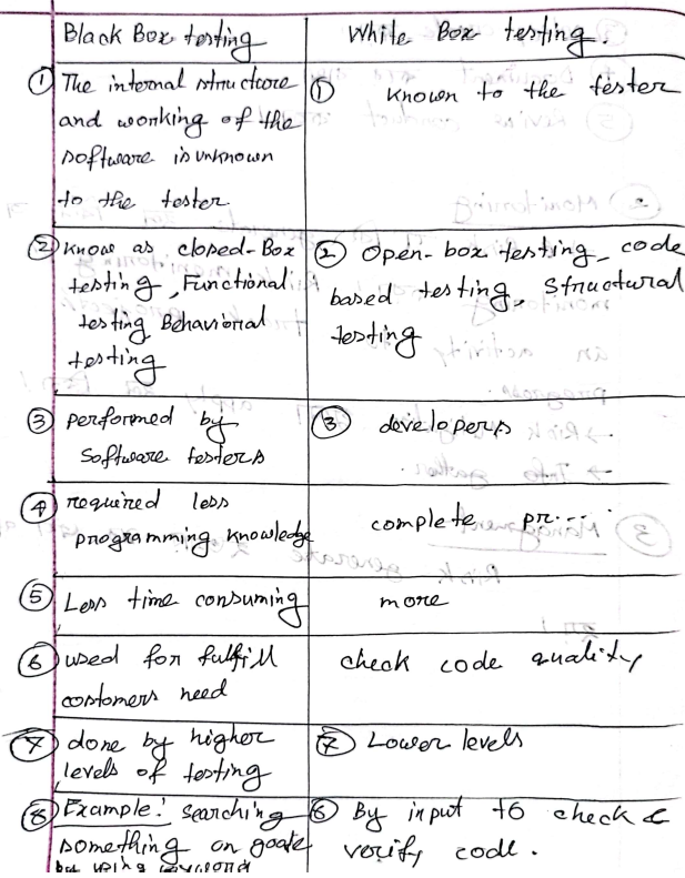
| Aspect | Black Box Testing | White Box Testing |
| Knowledge | No internal structure knowledge; focuses on input/output. | Knows internal structure and code. |
| Also Known As | Functional, data-driven, closed-box, behavioral. | Structural, glass box, code-based, transparent. |
| Programming Knowledge | Minimal required. | Complete knowledge required. |
| Testing Levels | System, acceptance testing. | Unit, integration testing. |
| Performed By | Software testers. | Software developers. |
| Time | Less time-consuming. | More time-consuming. |
| Basis | External expectations. | Internal code workings. |
| Testing Approach | Trial and error; tests data domains. | Tests internal boundaries and code paths. |
| Example | Search on Google. | Verify loops with input keywords. |
Unit Testing
- Definition: The first level of testing, where individual units (functions, methods, modules, or objects) are tested in isolation.
- Also Known As: Component testing.
- Performed By: Software developers.
- Testing Technique: White box testing.
- SDLC Phase: Coding phase.
- Tools: JUnit, NUnit, PHPUnit, EMMA, JMockit.
Purpose
- Verify code correctness and enable quick changes.
- Test every function and procedure.
- Fix bugs early to save costs.
- Aid documentation and code reuse.
- Improve software efficiency.
Unit Testing in Object-Oriented Context
- Tests packages, classes, methods, subclasses, and attributes (public, private, protected).
- Example: Test individual modules (e.g., login, search, payment) in a project.
Advantages
- Modular testing without waiting for other components.
- Focuses on unit functionality.
- Early issue detection improves quality.
- Enhances development efficiency.
Disadvantages
- Time-consuming to create and maintain test cases.
- Limited to individual units, not interactions.
- Requires ongoing maintenance with code changes.
Integration Testing
- Definition: The second level of testing, where integrated modules are tested as a group to verify communication and functionality.
- Also Known As: Thread testing, string testing.
- Performed By: Developers and testers.
- Goal: Ensure correctness and interaction among modules.
- Tools: Selenium, PyTest, JUnit, Jasmine, Steam, Mockito.
Purpose
- Verify differing programming logic across modules.
- Check database interactions.
- Address untested requirement changes.
- Detect module incompatibilities.
- Ensure hardware-software compatibility.
Example
- Gmail Application:
- User 1: Logs in, composes, and sends mail to User 2; saves to Draft or Sent Items.
- User 2: Logs in, checks Inbox, verifies mail receipt, replies if needed, logs out.
Types
- Incremental Integration Testing:
- Modules are integrated and tested one by one in ascending order.
- Tests data flow and function correctness.
- Subtypes:
- Top-Down:
- Starts with top-level modules, moving downward.
- Uses stubs (dummy programs) for missing lower modules.
- Prioritizes critical modules for early flaw detection.
- Bottom-Up:
- Starts with lowest modules, moving upward.
- Uses drivers (dummy programs) for missing higher modules.
- Allows simultaneous testing of subsystems.
- Top-Down:
- Example (Flipkart Application):
- Flow: Login → Home → Search → Add to Cart → Payment → Logout.
- Non-Incremental Integration Testing (Big Bang Testing):
- Integrates and tests all modules at once after individual testing.
- Suitable for smaller systems.
- Difficult to pinpoint errors due to lack of parent-child hierarchy.
Incremental vs. Non-Incremental Testing
| Aspect | Incremental Testing | Non-Incremental Testing |
| Integration Approach | Tests modules gradually. | Tests all modules at once. |
| Planning | Requires step-by-step planning. | Simpler, one-time planning. |
| Resource Efficiency | Uses more resources (separate tests). | Uses fewer resources (single test). |
| Issue Detection | Early detection with progressive testing. | Late detection due to bulk testing. |
| Complexity | Manages smaller pieces, less complex. | More complex due to testing everything. |
Conclusion
Software testing ensures a product is reliable, functional, and meets user needs. Key principles guide defect detection, while test cases verify functionality. White box testing examines code structure, black box testing focuses on functionality, unit testing isolates components, and integration testing verifies module interactions. Understanding these concepts, techniques, and examples is critical for exam success and effective software development.
Testing and Quality Assurance Exam Notes
1. System Testing
- Definition: Validates the fully integrated software product to ensure it meets end-to-end specifications.
- Type: Black-box testing by Quality Assurance (QA) team during testing phase.
- Focus: Functionality, accuracy, quality, expected output, overall behavior (not internal workings).
- Tools: Selenium, LoadRunner, JMeter, Microsoft Test Manager, SoapUI.
- Tool Choice Factors: Technology, project size, budget, testing requirements.
- Example: Testing an e-commerce app’s checkout process for correct functionality.
- Key Point: Ensures the complete system works as intended.
2. Importance of System Testing
- Benefits:
- Improved Quality: Works across platforms/environments.
- Error Reduction: Exposes errors missed in unit/integration testing.
- Cost Savings: Reduces unexpected costs/delays.
- Security: Identifies vulnerabilities to protect user data.
- Customer Satisfaction: Enhances user experience, builds confidence.
- Performance: Tracks memory, CPU usage, and system behavior.
- Example: System testing ensures a banking app is secure and performs well.
- Key Point: Critical for quality, security, and cost-effective delivery.
3. Types of Software Testing
- Performance Testing: Measures speed, load time, stability, reliability, response times.
- Example: Testing app response under heavy user load.
- Load Testing: Evaluates performance under real-life extreme loads (e.g., throughput, user count).
- Example: Simulating 10,000 users on a website.
- Usability Testing: Assesses ease of use, user error rates, task success, and satisfaction.
- Example: Checking if users can navigate an app intuitively.
- Regression Testing: Ensures new changes don’t introduce defects or reintroduce old bugs.
- Example: Retesting after a software update.
- Migration Testing: Verifies system works after infrastructure changes.
- Example: Moving an app to a new server without issues.
- Functional Testing: Identifies missing functions to improve system quality.
- Example: Checking if all required features (e.g., login) work.
- Recovery Testing: Tests system recovery from errors/crashes.
- Example: Ensuring an app restarts after a crash.
- Stress Testing: Tests robustness under extreme loads.
- Example: Testing app behavior with overloaded servers.
- Software & Hardware Testing: Checks compatibility between software and hardware.
- Example: Ensuring an app runs on specific devices/OS.
- Key Point: Each type targets specific system aspects for comprehensive testing.
4. System Testing Example
- Test Cases:
- Functionality: Input field accepts up to 20 characters (Expected: All characters valid).
- Security: Password rules enforced (Expected: Valid passwords accepted).
- Usability: Links work correctly (Expected: Links navigate to correct pages).
- Example: Testing a login page for character limits, password security, and link functionality.
- Key Point: Test cases verify specific system behaviors.
5. Acceptance Testing
- Definition: Final testing before release, performed by end-users/clients.
- Type: Black-box testing (also called User Acceptance Testing, Functional Acceptance Testing, Red Box Testing).
- Environment: User/live environment or real-time scenarios.
- Purpose: Ensures software meets user expectations and requirements.
- Tools: Fitness Tools, Watir.
- Example: Client testing an app’s payment feature in a live-like setup.
- Key Point: Validates software for real-world use.
6. Importance of Acceptance Testing
- Benefits:
- Identifies bugs missed during development.
- Confirms product meets client/user expectations.
- Builds client confidence through direct involvement.
- Ensures bug-free delivery.
- Satisfies SRS functionalities.
- Example: Ensuring a shopping app meets client needs before launch.
- Key Point: Critical for client satisfaction and final validation.
7.(types of acceptance testing)
- User Acceptance Testing (UAT):
- Performed from end-user perspective.
- Checks if software meets user requirements in a production-like environment.
- Focuses on functionality, not bugs.
- Example: Users testing a mobile app’s navigation.
- Business Acceptance Testing (BAT):
- Verifies software meets business requirements and operational needs.
- Focuses on business risks and financial factors.
- Example: Ensuring an app supports business goals in a dynamic market.
- Regulations Acceptance Testing (RAT):
- Ensures compliance with regional rules/regulations.
- Non-compliance holds the product owner accountable.
- Example: Checking if an app adheres to GDPR regulations.
- Key Point: Each type ensures specific acceptance criteria are met.
8. Alpha vs. Beta Testing
- Alpha Testing:
- By internal testers (skilled employees).
- Uses white-box and black-box techniques.
- Focuses on bugs/errors, not in-depth reliability/security.
- Long execution cycles, done near development end.
- Example: Internal team testing app before beta.
- Beta Testing:
- By clients/end-users in real-time environments.
- Black-box testing only.
- Checks reliability, security, robustness.
- Short cycles (few weeks), final test before release.
- Example: Users testing a game app for real-world performance.
- Key Point: Alpha improves quality pre-beta; beta ensures readiness for users.
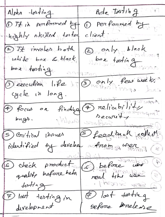
9. Verification vs. Validation
- Verification:
- “Are we building the software right?” (Static testing).
- Checks documents, design, code by QA/developers.
- Methods: Inspections, reviews, walkthroughs.
- Finds bugs early, no code execution.
- Example: Reviewing code for correct syntax.
- Validation:
- “Are we building the right software?” (Dynamic testing).
- Tests actual product by testing team.
- Includes functional, system, integration, UAT.
- Involves code execution, catches missed bugs.
- Example: Testing a chat app’s features (chatting, calls, sharing).
- Key Point: Verification ensures correctness; validation ensures user needs are met.
10. Defect/Bug
- Definition: Errors causing abnormal software behavior due to design/coding issues.
- Variation: Difference between actual and expected results.
- Defect Life Cycle: States a defect goes through for systematic fixing.
- Performed By: Developers and testers.
- Tools: JIRA, Trac, Redmine.
- Example: A login failure due to incorrect code is a defect.
- Key Point: Defects disrupt functionality; life cycle ensures efficient fixes.
11. Defect Life Cycle
- Stages:
- New: Tester identifies defect, sends document to developers.
- Assigned: Defect assigned to developer team.
- Open: Developers fix or mark as Duplicate/Rejected/Deferred.
- Fixed: Developer corrects code to remove defect.
- Retest: Testers verify if defect is fixed.
- Reopened: If defect persists, cycle restarts.
- Verified: Tester confirms defect is fixed.
- Closed: Issue closed after verification.
- Example: A bug in payment processing is identified, fixed, and verified.
- Key Point: Systematic process to track and resolve defects.
12. Testing vs. Debugging
- Testing:
- Finds bugs/errors, done by testers.
- Manual or automated, based on testing levels (unit, integration, system).
- No programming knowledge required.
- Part of SDLC, post-coding.
- Example: Testing a form for input errors.
- Debugging:
- Fixes bugs found during testing, done by developers.
- Always manual, requires programming knowledge.
- Subset of testing, starts with test case execution.
- Example: Fixing code causing form input errors.
- Key Point: Testing identifies issues; debugging resolves them.
13. Software Quality
- Definition: Software’s ability to function as per user requirements and SRS.
- Aspects:
- Good Design: Attractive visualization.
- Durability: Long-term functionality.
- Consistency: Works across platforms/devices.
- Maintainability: Easy bug fixes/feature additions.
- Value for Money: Worth the investment.
- Example: A durable, user-friendly app justifies its cost.
- Key Point: Ensures functionality and user satisfaction.
14. Software Quality Dimensions
- Dimensions:
- Maintainability: Ease of modifying (features, bugs).
- Portability: Transferable across locations.
- Functionality: Performs specified functions.
- Performance: Speed under load.
- Compatibility: Works across devices/OS/browsers.
- Usability: Ease of use.
- Reliability: Error-free under stated conditions.
- Security: Protects against unauthorized access.
- Example: A secure, portable app works on multiple devices.
- Key Point: Dimensions define quality standards.
15. Factors Affecting Software Quality
- Product Operation:
- Correctness, Reliability, Efficiency, Integrity, Usability.
- Product Revision:
- Maintainability, Flexibility, Testability.
- Product Transition:
- Portability, Reusability, Interoperability.
- Example: Usability ensures intuitive UI; portability supports multiple platforms.
- Key Point: Factors ensure operational, revisable, and transferable quality.
16. Software Quality Metrics
- Customer Problem Metrics:
- Measures customer-reported issues.
- Formula: PUM = Total problems ÷ Total license months.
- Customer Satisfaction Metrics:
- Rates satisfaction (Very Satisfied to Very Dissatisfied).
- Software Maintenance Metrics:
- Tracks defects post-release in customer environment.
- Example: PUM calculates issues per license month for an app.
- Key Point: Metrics quantify quality and satisfaction.
17. Software Quality Management (SQM)
- Definition: Process ensuring software meets national/international standards (e.g., ANSI, IEEE, ISO).
- Needs:
- Delivers high-quality products on time.
- Builds stakeholder trust.
- Ensures customer satisfaction.
- Example: SQM ensures an app meets ISO standards for quality.
- Key Point: Maintains high standards for delivery and trust.
18. How to Achieve Software Quality
- Quality Assurance (QA):
- Ensures system meets requirements/expectations.
- Defines standards/methodologies for development.
- Covers correctness, efficiency, flexibility, etc.
- Quality Control (QC):
- Ensures quality parameters are met.
- Focuses on timely, cost-accurate delivery.
- Quality Planning:
- Selects/modifies standards for a project-specific quality plan.
- Example: QA defines app standards; QC verifies functionality.
- Key Point: QA, QC, and planning ensure quality delivery.
19. Quality Assurance vs. Quality Control
- Quality Assurance (QA):
- Proactive, process-oriented, prevents defects.
- Defines standards, involves full SDLC.
- Done by all team members, no code execution.
- Example: Setting coding standards for an app.
- Quality Control (QC):
- Reactive, product-oriented, identifies/fixes defects.
- Verifies standards, involves testing life cycle.
- Done by testing team, involves code execution.
- Example: Testing app for defects post-development.
- Key Point: QA prevents issues; QC ensures product quality.