Software Engineering
| Created by | Borhan |
|---|---|
| Last edited time | |
| Tag | Year 3 Term 2 |
Resources
https://nptel.ac.in/courses/106105087
https://www.youtube.com/watch?v=IHx9ImEMuzQ&list=PLQ-nEJNYlEV29CBLzIDxcogm6CEZjVad2&index=1
https://www.youtube.com/watch?v=ErCgOsea_5I
Introduction to Software Engineering
What is Software Engineering ?
- Engineering approach to develop software
- Systematic collection of past experience
- techniques
- methodologies
- guidelines
- IEEE Definition : Software engineering is the application of a systematic, disciplined, quantifiable approach to the development, operation, and maintenance of software, that is the application of engineering to software.
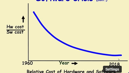
Software Crisis
- Fail to meet user requirements
- Expensive
- Difficult to alter, debug and enhance
- Often delivered late
- Use resources non-optimally
Which factors are contributing to the software crisis ?
- Larger problems
- Poor project management
- Lack of adequate training in software engineering
- Increasing skill shortage
- Low productivity improvements
Programming an art or engineering ?
Initially every technology starts in an art form, slowly becomes a craft and then graduates into an engineering approach.
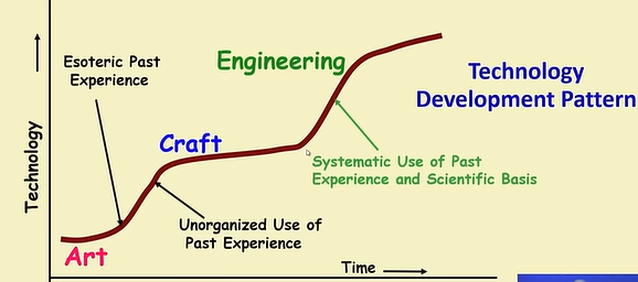
- Heavy use of past experience:
- Past experience is systematically arranges
- Theoretical basis and quantitative techniques
- Many are just thumb rules
- Tradeoff between alternatives
- Pragmatic approach to cost-effectiveness
Exploratory Software Development
- Early programmers used exploratory (also called build and fix) style
- A dirty program is quickly developed
- The bugs are fixed and when they noticed
- Similar to how a junior student develops programs.
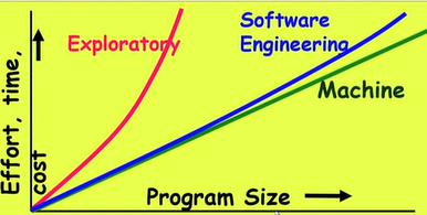
What is wrong is Exploratory style?
- Can successfully used for small programs
- The exponential growth of effort, cost and time with problem size
- Unmaintainable code
- Very difficult to use this style in team development environment
How it exponentially increases ? → Human Cognitive System (Short term and long term memory) → Huge numbers of variables in large projects → Quickly exceeds the grasping power of an individual → Require an unduly large effort to master the problem
How software engineering solves this ?
Software Engineering principle extensively use techniques specifically targeted to overcome the human cognitive limitations.
Two important principle profusely Used: (Two fundamentals techniques to handle the complexity)
- Abstraction
- Simplify a problem by omitting unnecessary details
- Focus attention on only one aspect of the problem and ignore other aspects and irrelevant details
- Also called Model Building
- Does every problem have a single abstraction ?
- Several abstractions of the same problem can be created.
- focus on some specific aspect and ignore others
- different types of models help understand different aspect of the problem
- For complex problems
- A single level of abstraction is inadequate
- A hierarchy of abstraction may have to be constructed
- Hierarchy of models
- A model in one layer is abstraction of the lower layer model
- An implementation of the model at the higher layer.
- Several abstractions of the same problem can be created.
- Decomposition
- Decompose a problem into many small independent parts
- The idea that each small part would be easy to grasp and therefore can be easily solved
- The full problem is solved when all the parts are solved.
- Any arbitrary decomposition of a problem may not help
- The decomposed parts must be more or less independent of each other
- Decompose a problem into many small independent parts
Why study Software Engineering ?
- To acquire skills to develop a large programs
- Handling exceptional growth in complexity with size
- Systematic techniques based on abstraction and decomposition
- Learn systemic techniques of
- Specification, design, user interface development, testing, project management, maintenance, etc.
- Appreciate issues that arise in team development
- To acquire skills to be a better programmer
- Higher productivity and better quality programs
Two types of software projects:
- Products (Generic software)
- Packaged Software : Prewritten software available for purchase
- Horizontal market software : Meets needs of many companies
- Vertical market software : designed for particular industry
- Packaged Software : Prewritten software available for purchase
- Services (Custom software)
- Software developed at some user’s requests
- Usually developer tailors some generic solution
- Software service is an umbrella term, includes
- Software customization
- Software maintenance
- Software testing
- Also contract programmers carrying out coding or any other assigned activities
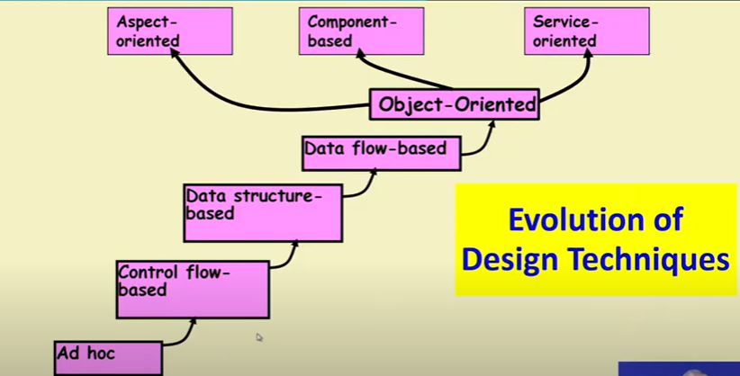
Emergence of Software Engineering Techniques
- Early Computer Programming (1950s)
- Assembly language, sizes limited to a few hundreds of lines
- build-and-fix style
- Higher-Level language (early 60s)
- FORTAN, ALGOL, COBOL
- reduce efforts greatly
- Still exploratory
- Control Flow Based design (late 60s)
- experienced programmer advised, “Pay particular attention to the design of the program’s control structure”
- Control Structure
- Sequence in which the program’s instruction are executed is called control structure
- Flow charting technique
- A program having a messy flow chart representation → difficult to understand and debug
- GO TO Statements makes control structure of a program messy
- Dijkstra published his article, “Goto Statement Considered Harmful” 1969
- Only three programming constructs are sufficient to express any programming logic (conclusively proved)
- sequence
- selection
- iteration
- Structured programming
- No goto statements, only the following constructs
- sequence
- selection
- iteration
- consists of modules
- Advantages
- Easier to read, understand and maintain
- Require less effort and time for development
- Less buggy
- No goto statements, only the following constructs
- Data Structure-Oriented Design (Early 70s)
- Program sizes increase → “it is more important to pay more attention to the design of data structure of a program” was discovered
- Jackson’s structured Programming (JSP) methodology
- Developed by Micheal Jackson, 1970s
- Program code structure should be correspond to the data structure
- Data Flow-Oriented Design (Late 70s)
- Data flow-oriented techniques advocate
- The data items input to a system must be identified
- Processing required on the data items to produce the required outputs should be determined
- Data flow-oriented techniques advocate
- Object Oriented Design (80s)
- Natural Objects
Life Cycle
A software life cycle model/Process model/Software Development Life cycle
- A descriptive and diagrammatic of software life cycle
- Identifies all the activities undertaken during product development
- Establishes a precedence ordering among the different activities
- Divides life cycle into phases
- Each life cycle phase consists of several activities
- structured analysis
- structured design
- design review
Why Model Life Cycle ?
- A graphical and written description
- helps common understanding of activities among the software develops
- helps to identify inconsistencies, redundancies and omissions in the development process
- helps in tailoring a process model for specific projects
A life cycle model
- defines entry and exit criteria for every phase
- A phase is considered to be complete
- only when all its exit criteria are satisfied
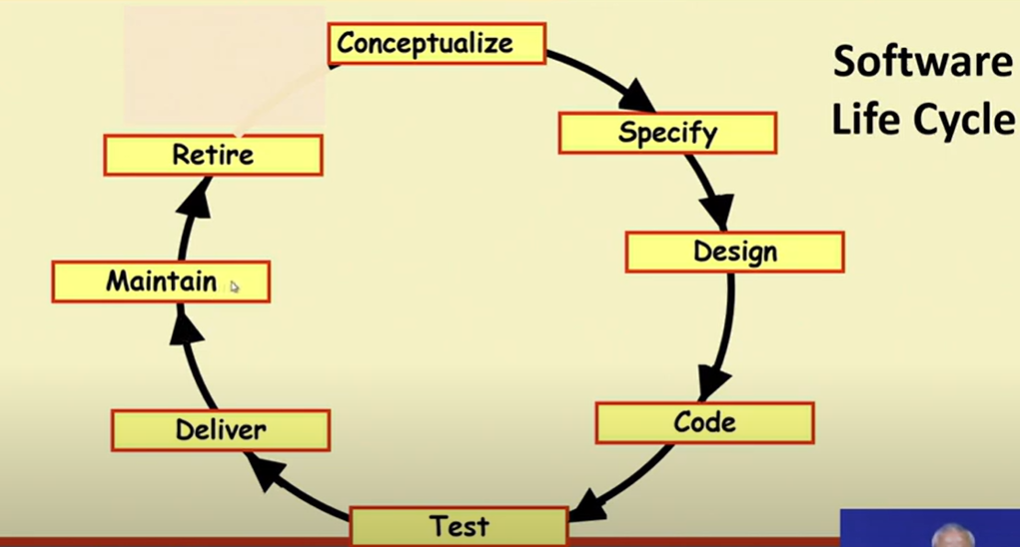
Software Life Cycle/Software Process
Series of identifiable stages that a software product undergoes during its life time:
- Feasibility study
- Requirements analysis and specification
- Design
- Coding
- Testing
- Maintenance
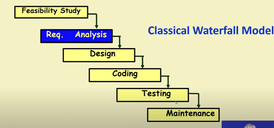
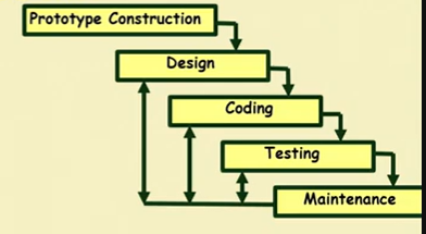
Classical Waterfall Model
- Classical Waterfall Model divides life cycle into following phases
- Feasibility Study
- 3 Main aspects
- Economic feasibility : also called cost/benefit feasibility
- Technical feasibility : Developer can do or not
- Schedule feasibility :
- The main aim is determining whether the software is
- Financially worthwhile
- Technically feasible
- Steps
- Roughly understand what customer wants
- Data which would be input to the system
- Processing needed to these data
- Output data to be produced by the system
- Various constraints on the behavior of the system
- ….
- Roughly understand what customer wants
- Activities During Feasibility Study
- Work out an overall understanding of the problem
- Formulate different solution strategies
- Examine alternate solution strategies in terms of:
- resource requires
- cost of development
- development time
- Perform a cost/benefit analysis
- Determine which solution is the best
- May also find that none solution is feasible due to high cost/resource constraints/ technical reasons
- Need to identify all costs like development costs, set-up, operational costs
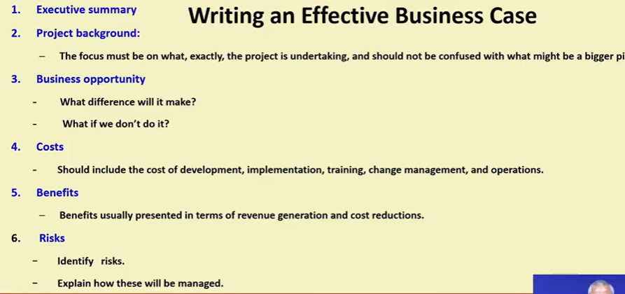
- When feasibility study is over, the project manager prepare a “business case”
- what are the costs and benefits
- 3 Main aspects
- Requirements analysis and specification
- Aims of the phase
- Understand the exact requirements of the customer
- Document them properly
- Two distinct activities
- Requirements gathering and analysis
- Gather requirements data from the customer
- Analyze the collected data to understand what customer wants
- Remove requirements problems
- Inconsistencies : one part contradicts with others
- Anomalies : Ambiguity
- Incompleteness : Missing
- Organize into a Software Requirements Specification (SRS) document
- Requirements Gathering
- Gathering relevant data : Usually collected from the end-users through interviews and discussions
- Requirements Analysis
- Ambiguities and contractions
- must be identified and resolved by discussion with the customers
- Requirement are organized and document in SRS
- Ambiguities and contractions
- Gather requirements data from the customer
- Requirements specification
- Requirements gathering and analysis
- Aims of the phase
- Design
- During design phase requirements specification is transformed into a form suitable for implementation in some programming language.
- Two commonly used approach
- Traditional approach
- Consists of two activities
- Structured analysis (typically carried out by using DFD)
- Structured Design
- High level design
- decompose the system into modules
- represent invocation relationship among the modules
- Detailed design
- data structure and algorithm for each module are designed
- High level design
- Consists of two activities
- Object Oriented approach
- First identify various objects occurring in the design
- Object Structure : Refined to obtain the detailed design
- OOD has several advantages
- Lower development effor
- lower development time
- better maintainability
- Traditional approach
- Coding and unit testing
- Each module of the design is coded
- Each module is unit tested
- Each module is documented
- Integration and system testing
- Integration Testing
- Different modules are integrated in planned manner
- Modules are usually integrated through a number of steps
- During each integration step
- the partially integrated system is tested
- Different modules are integrated in planned manner
- System Testing
- Ensure that the developed system functions according to its requirements as specified in the SRS document
- Integration Testing
- Maintenance
- Requires much more effort then effort to develop the product itself
- Development effort to maintenace effort is typically 40:60
- Types of maintenance/Why maintenance is needed
- Corrective Maintenance : Correct errors which were not discovering during the product development phase
- Perfective maintenance : Improve implementation and enhance functionalities of the system
- Adaptive maintenance: Port software to a new environment (e.g. to a new computer or to a new operating system)
- Feasibility Study
- Phases between feasibility and testing → Development phase
- Among all phases, Maintenance phase consumes maximum effort
- Among development phases → Testing phase consumes maximum effort
Why it is called Waterfall model ?
[…]
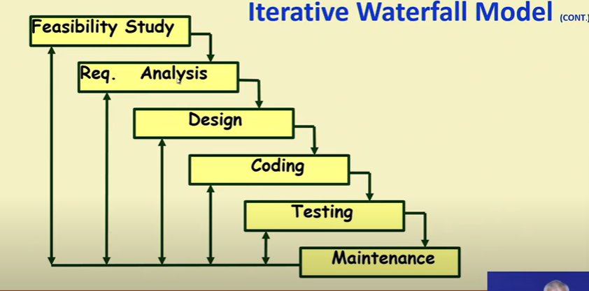
- Classical waterfall model is idealistic :
- Assumes that no defect is introduced during any development activity. In practice : defects do get introduced in almost every phase of the life cycle.
- the later the phase in which the defects gets detected, the more expensive is its removal, why ? → We need redesign every phase from the defected phase.
Phase Containment of Errors
- Reason : rework must be carried out not only to hte design but also to code and test phases
- The principle of detecting errors as close to its point of introduction as possible is know as phase containment of errors
- Error should be detected in the same phase in which they introduced it will cost least.
- Iterative waterfall model is by far the most widely used model
- almost every other model is derived from the waterfall model.
Advantages
- Easy to understand, use
- Provided a reference to inexperienced staff
- Milestones are well understood by the team
- provides requirement stability
- facilitates strong management control
Disadvantages
- All requirements must be known upfront → in most projects requirements change occurs after project start
- Deliverables created for each phase are considered frozen inhibits flexibility
- Can give a false impression of progress
- Integration is one big bang at the end
- Little opportunity for customer to pre-view the system
- Does not support overlapping phases
When to use the waterfall model ?
- Requirements are well known and stable
- Technology is understood
- Experienced team
V Model
- It is a variant of Waterfall Model
- emphasizes verification and validation
- V&V activities are spread over entire life cycle
- In evert phase of development
- Testing activities are planned in parallel with development
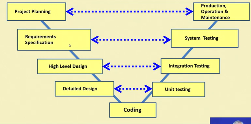
Left = Development phase, Right=Testing phase
- V Model Steps
- Planning
- Requirement Analysis and Specification, System Test design
- High level design, Integration test design
- Detailed Design, Unit test design
Strengths
- Starting from early stages of software development
- Emphasizes planning for verification and validation of the software
- Each deliverable is made testable
- Easy to use
Weaknesses
- The requirement are frozen before the project starts, there’s no scope changing the requirements
- Does not support overlapping phases
- Does not handle iterations or phases
- Does not easily accommodate later changes to requirement
- Does not provide support for effective risk handling
When to use V model
- Natural choice for system requiring reliability
- embedded control applications, safety-critical softwarea
- All requirements are known up-front
- Solution and technology are known
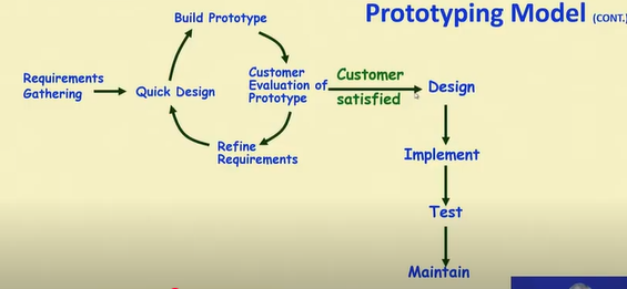
Prototyping Model
- A derivative of waterfall model
- Before starting actual development
- A working prototype of the system should be built first
- A prototype is toy implementation of a system
- Limited functional capabilities
- low reliability
- inefficient performance
Reasons for prototyping
- Learning by doing: useful where requirement are partially known
- Improved communication
- Improved user involvement
- Reduced need for documentation
- Reduced maintenance costs
Advantages
- The resulting software is usually more usable
- User needs are better accommodated
- The design is of higher quality
- The resulting software is easier to maintain
- Overall, the development incurs less cost
Disadvantages
- For some project, it might be expensive
- Susceptible to over-engineering
Major difficulties of Waterfall based Models
- Difficulty in accommodating changes request during development (the requirement is frozen before starting the development phase)
- 40% of the requirements change during development
- High cost incurred in developing custom applications
- Heavy weight processes
- Requirements for the system are determined at the start
- Are assumed to be fixed from that point on
- Long term planning is made-based on this
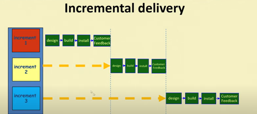
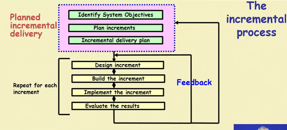
Incremental Model
Characteristics
- Builds system incrementally
- Consists of a planned number of iterations
- Each iteration produces a working program
Benefits
- Facilitates and manage changes
- Foundation of agile technique and the basis for
- Rational Unified Process (RUP)
- Extreme Programming (XP)
Developer Perspective
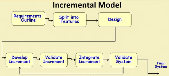
- Requirements outline
- Split into Features
- Design
- Develop Increment
- Validate Increment
- Integrate Increment
- Validate System
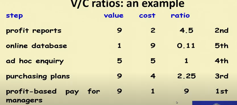
Which step first?
- Some steps will be pre-requisite because of physical dependencies
- Others may be in any order
- Value to the cost ratios may be used
- V/C (Value/cost) where
- V is a score 1-10 representing value to customer
- C is a score 1-10 representing cost to developer
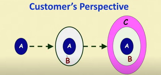
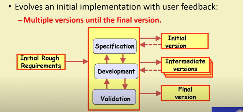
Evolutionary Model
- First develop core modules of the software
- The initial skeletal software is refined into increasing levels of capability : (iterations)
- By adding new functionalities in successive versions
Activities in iteration
- Software developed over several mini waterfalls
- The result of a single iteration
- ends with delivery of some tangible code
- An incremental improvement of the software — leads to evolutionary development
Evolutionary model with iteration
- Outcome of each iteration : tested, integrated, executable system
- Iteration length is short and fixed
- usually between 2 and 6 weeks
- development takes many iterations
- Does not “freez” reqyurements and then conservatively design:
- Successive versions
- Functioning systems capable of performing some useful work
- A new release may include new functionality
Advantages
- Users get a chance to experiment with a particular developed system
- Helps finding exact user requirement
- Core modules get tested thoroughly
- Better management of complexity
- Better management of changing requirements
- Training can start on an earlier release
- Frequent releases allow developers to fix problem quicker
Disadvantages
- The process is intangible
- No regular, well defined deliverables
- The process in unpredictable
- Hard to manage, scheduling workforce
- System are rather poorly structured
- System may not even converge to a final version
RAD Model
- Rapid Application Developement model
- Also known as rapid prototying model
- Major aims
- Decrease the time and cost
- Facilitate accommodating change request as early as possible
Important underlying principle
- A way to reduce development time and cost and yet have flexibility to incorporate changes:
“Make only short term plans and make heavy reuse of existing code”
Methodology
- Plans area made for one increment at a time
- The time planned for each iteration is called time box
- Each Iteration (increment)
- Enhances the implemented functionality of the application a little
- During each iteration
- A quick-and-dirty prototype style software for some selected functionality is developed
- The customer evalutes the prototype and give his feedback
- The prototype is refined based on the customer feedback
How does RAD facilitate faster developement ?
- Create prototypes using specialized tools
- visual style of development (like drag and drop)
- Use of reusable components
- Use of standard apis
Suitable for
- Customized product developement for one or two customers only
- Performance and reliability are not critical
- the system can be split into several independent modules
Not suitable for
- High performance or reliability requires
- few flug-in component are available
- the system cannot be modularized
- no precedence for simpilar products exists
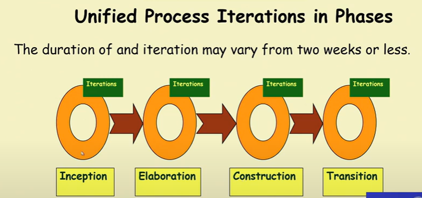
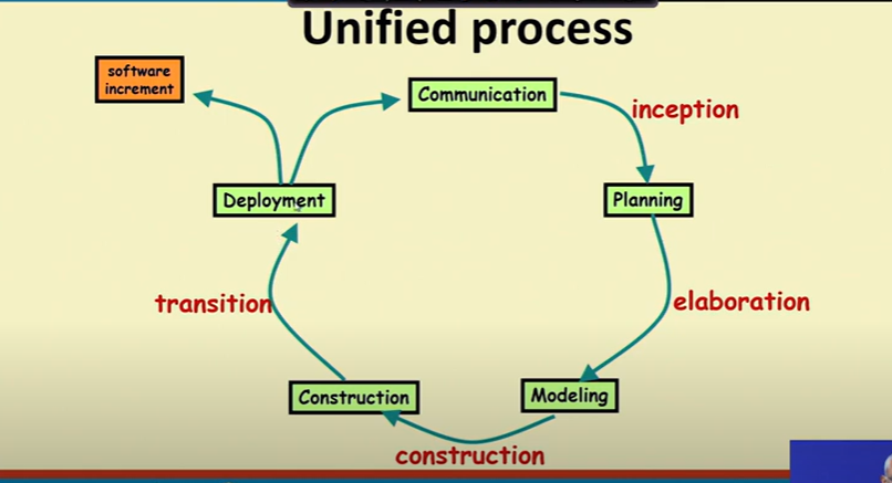
Unified Process
- Developed by Ivar Jacobson, Grady Booch and James Rumbaugh
- Incremental and iterative
- Rational Unified Process (RUP) is version tailored by Rational Software, acquired by IBM , in Feb 2003
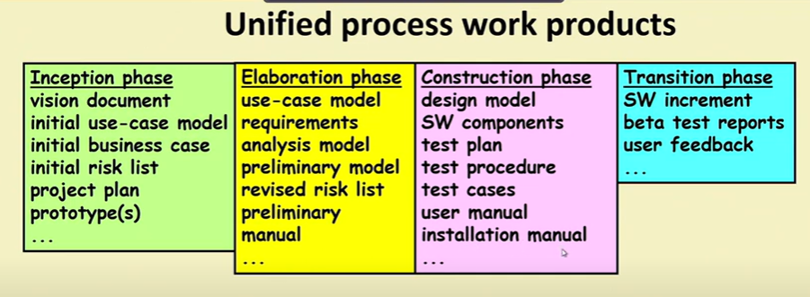
- Four phases
- Inception
- Eloboration
- Construction
- Transition
Inception Activities
- Formulate scope of project
- risk management, staffing, project plan
- Synthesize a candidate architecture
Outcome of Inception Phase:
- Initial requirement capture
- Cost benefit analysis
- Initial Risk analysis
- project scope deinition
- defining a candidate architecture
- development of a disposable prototype
- initial use case model
- first pass domain model
Spiral/Mata Model
- Proposd by Bohem in 1988
- Phases
- Determining objectives, alternatives and contraints
- Risk Assessment and reduction
- Develop and validation
- Review and planning
📌 Requirements Engineering Overview
Definition:
Requirements are formal statements about what a software system should do, how it should behave, what properties and constraints it must satisfy, and the qualities it must possess.
🔍 Requirements Analysis
Requirements analysis involves understanding what the system should do, how it interacts with other systems, and what limitations or constraints exist.
Key Goals:
- Define how the software should operate.
- Determine how it will interface with other systems.
- Identify any technical, organizational, or legal constraints.
📘 Phases of Requirements Engineering
"I Enjoy Every New Software Version"
| Phase | Purpose |
| Inception | Ask basic questions to understand: - the problem - who needs the solution - the expected solution - communication effectiveness |
| Elicitation | Gather requirements from all stakeholders (users, customers, developers, etc.) |
| Elaboration | Build detailed models to capture: - data requirements - functional requirements - behavioral requirements |
| Negotiation | Prioritize and resolve conflicts among requirements. Agree on a feasible version of the system |
| Specification | Represent requirements using: - written documents - models - mathematical formulas - use-cases - prototypes "Write More Formally Using Prototypes” |
| Validation | Review the requirements to find: - errors or misunderstandings - Clarification needed - unclear or missing information - inconsistencies - unrealistic/conflicting expectations "Every Cat Might Ignore Rain” |
🗂️ Types of Requirements
"Big Smart Students Find New Topics"
| Type | Explanation |
| Business Requirements | High-level goals, objectives, and needs of the organization. |
| Stakeholder Requirements | Expectations and needs of each stakeholder group (users, customers, etc.). |
| Solution Requirements | Specific features and functions that the system must include. |
| → Functional Requirements | What the system should do (features, user interactions, business rules). |
| → Non-Functional Requirements | Qualities the system should have (performance, security, reliability, etc.). Also called quality attributes. |
| Transition Requirements | Requirements needed for moving from the current system to the new one (e.g., data migration, training). |
✅ Functional Requirements
🔹 Definition:
Functional requirements describe how the system should behave under specific conditions. They define features, actions, and rules that the system must implement.
🔹 Key Characteristics:
- Must be precise and clear for both developers and stakeholders.
- Describe what the system should do.
- Often documented using use cases.
🔹 Examples of Functional Requirements:
- Business rules
- Transaction corrections, adjustments, cancellations
- Administrative functions
- Authentication
- Authorization levels
- Audit tracking
- Reporting requirements
- External interfaces
- Certification requirements
- Historical data
✅ Non-Functional Requirements (NFRs)
🔹 Definition:
Non-functional requirements define the quality attributes of a system. They focus on how well the system performs, rather than what it does.
🔹 Key Characteristics:
- Define system standards, constraints, and qualities.
- Used to evaluate system performance, usability, and reliability.
🔹 Examples of Non-Functional Requirements:
| Category | Examples |
|---|---|
| Performance | Response time, throughput, resource utilization |
| Capacity | Data volume the system must handle |
| Availability | Uptime percentage or hours |
| Reliability | Frequency of failure or errors |
| Recoverability | Ability to restore from failures |
| Maintainability | Ease of making updates |
| Serviceability | Ease of system support |
| Security | Data protection and access control |
| Regulatory | Legal or industry compliance |
| Manageability | Ease of system monitoring and management |
| Environmental | Constraints based on the operating environment |
| Data Integrity | Accuracy and consistency of stored data |
| Usability | User-friendliness and interface design |
✅ Elements of the Analysis Model
🔹 1. Scenario-Based Elements
| Type | Explanation |
| Functional | Narratives describing software functions |
| Use-Case | Interactions between an actor and the system |
🔹 2. Class-Based Elements
- Extracted from the scenarios
- Define data and objects within the system
🔹 3. Behavioral Elements
- Describe how the system behaves dynamically
- Example: State diagrams
🔹 4. Flow-Oriented Elements
- Represent the flow of data
- Example: Data Flow Diagrams (DFDs)
✅ Use Cases
🔹 Definition:
A use case describes the interaction between a user (actor) and the system to achieve a specific goal.
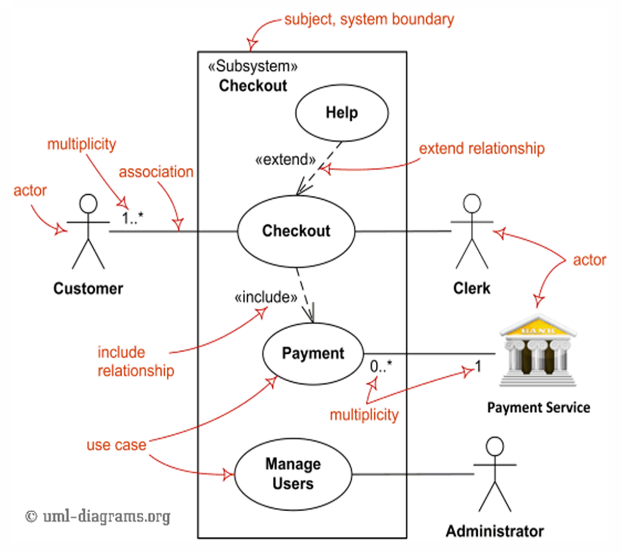
🔹 Main Components:
| Element | Description |
| Actors | Users or systems that interact with the system. They can be primary or secondary. |
| System | Behaviors/functions the system must support. |
| Goals | The purpose of the interaction (what the actor wants to achieve). |
🔹 Actor Types:
| Actor Type | Role |
| Primary | Initiates the use case, interacts directly with the system (left side of the diagram). |
| Secondary | Supports the system, used by the system but doesn’t initiate interaction (right side of the diagram). |
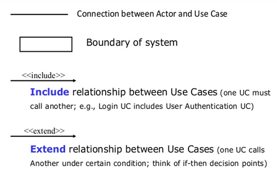
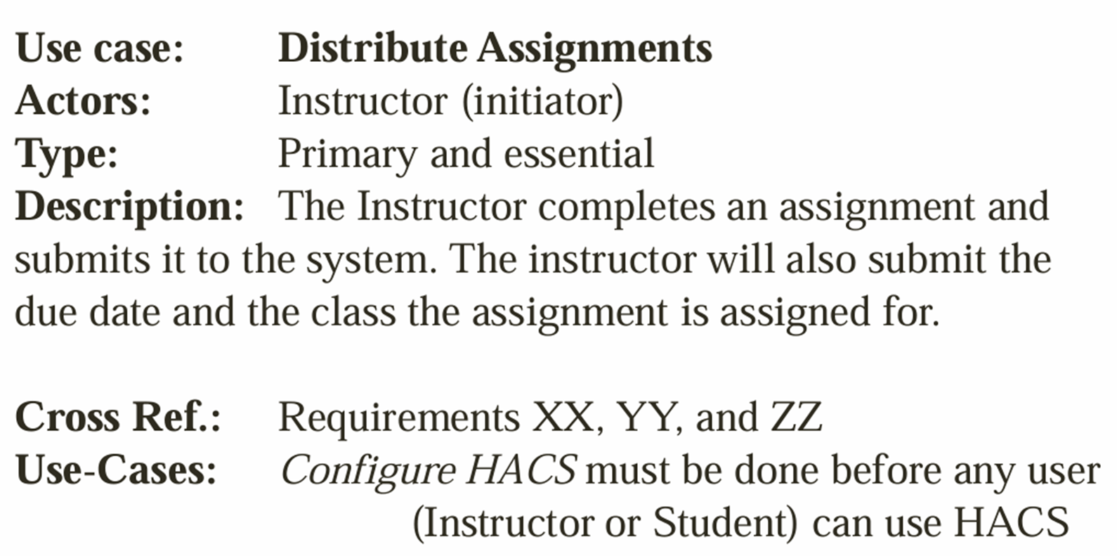
🔹 Representation Formats:
- Use Case Specification (text-based description of steps, actors, outcomes)
- Use Case Diagram (visual representation using UML notation)
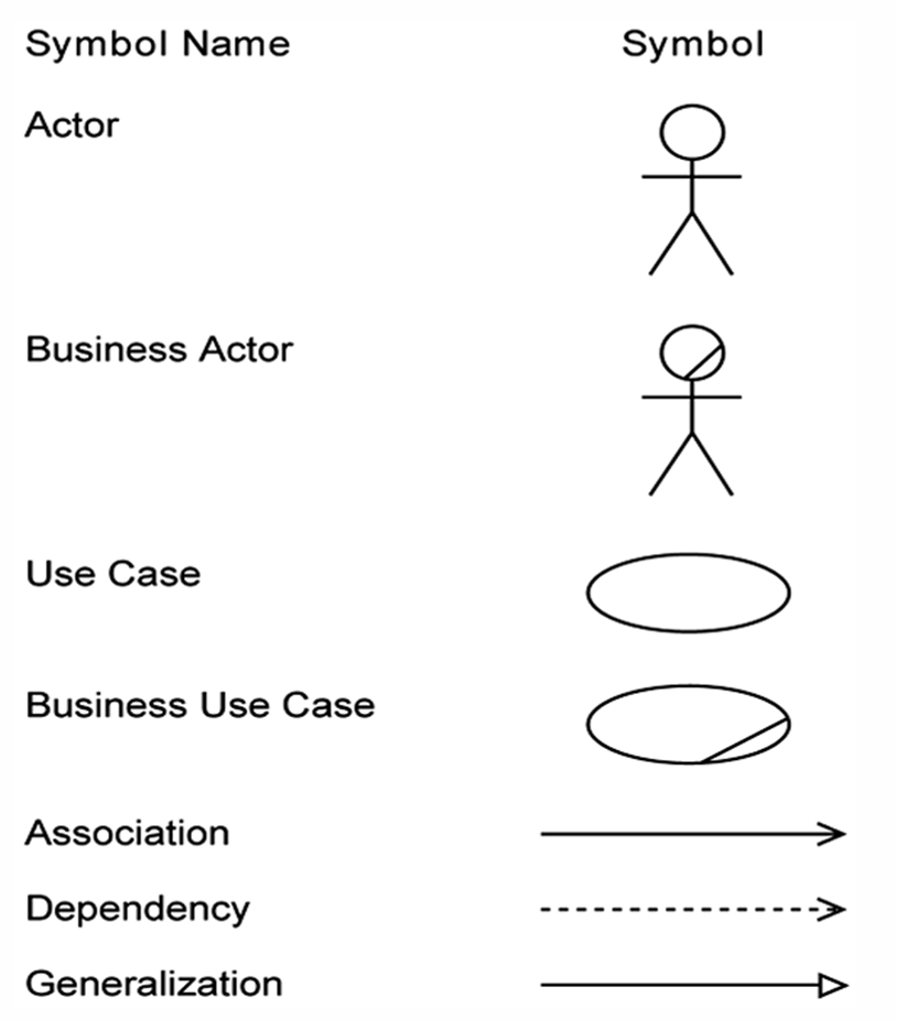
The Unified Modeling Language (UML) is a standardized visual modeling language used in software engineering to specify, visualize, construct, and document the artifacts of a software system.
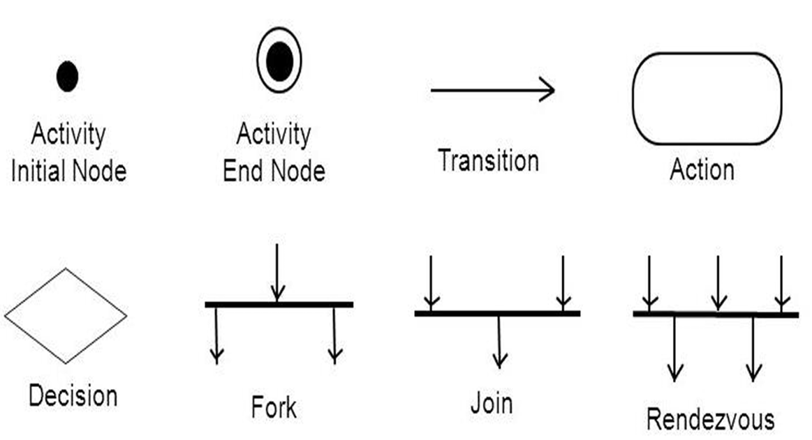
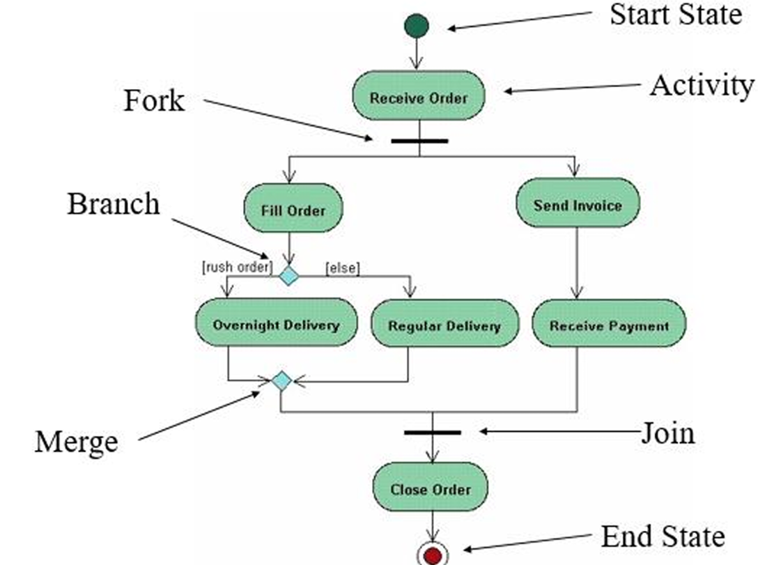
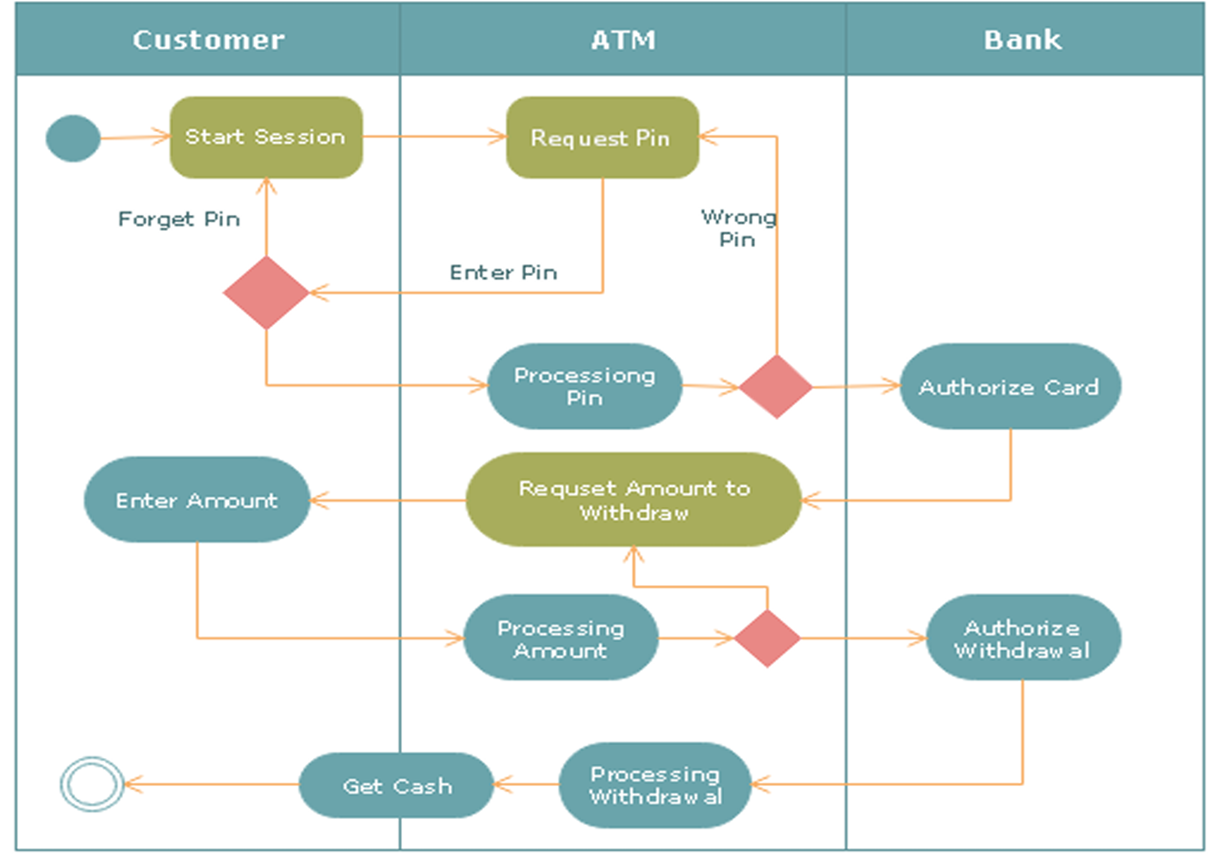
1. Activity Diagram
Definition: An activity diagram is a type of UML diagram that illustrates the dynamic aspects of a system by showing the workflow of control from one activity to another. It emphasizes the sequence and conditions for coordinating lower-level behaviors.
- Activity Diagrams to illustrate the flow of control in a system and refer to the steps involved in the execution of a use case.
Purpose: To model the flow of control in a system, often used to describe the steps in the execution of a use case.
Key Points:
- Represents parallel and conditional paths.
- Focuses on flow conditions and transitions.
- Useful for modeling business processes and workflows.
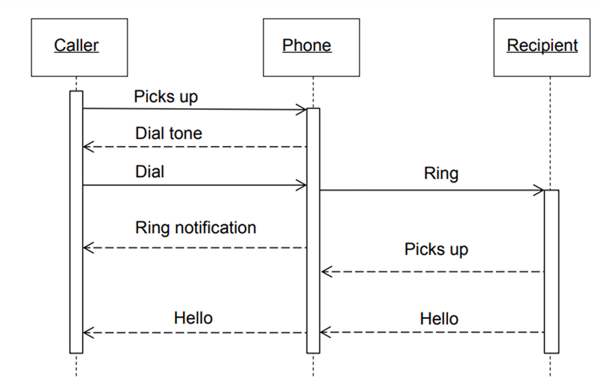
2. Sequence Diagram
Definition: A sequence diagram describes the interaction between objects in a sequential order. It shows how objects communicate with each other through messages over time.
Purpose: To represent how different parts of the system interact in a particular scenario.
Key Components:
- Lifelines: Vertical dashed lines that represent an object's presence over time.
- Messages: Horizontal arrows that show the communication between objects.
Use:
- To describe real-time specification and usage scenarios.
- To model the logic of a complex operation or workflow.
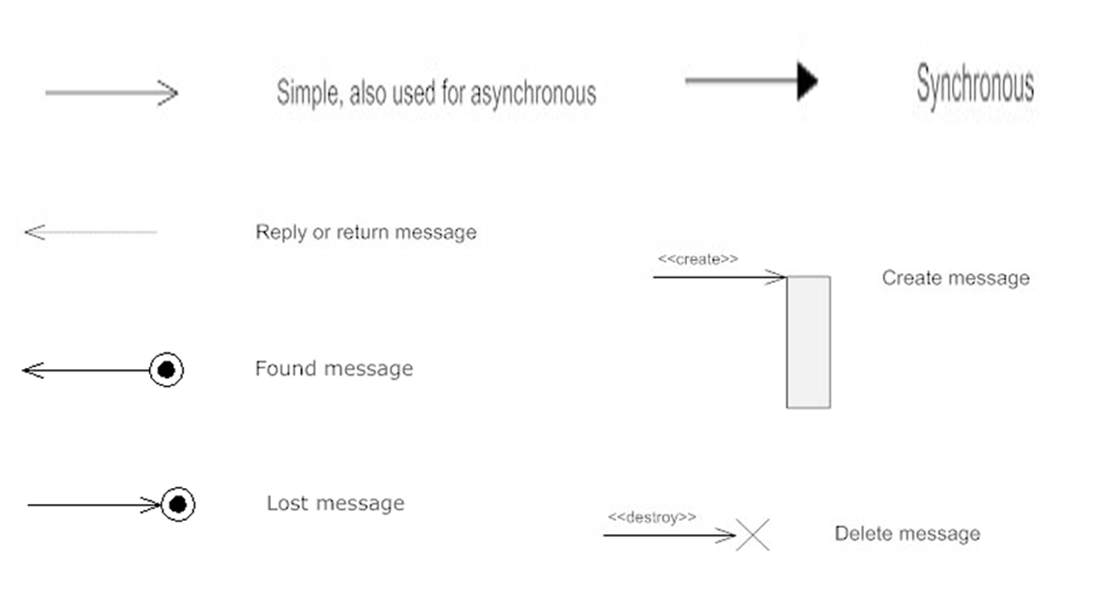
Types of message
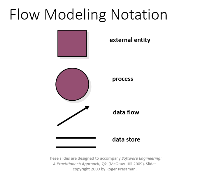
3. Data Flow Diagram (DFD)
Definition: A DFD is a graphical representation that illustrates the flow of data through a system. It depicts how input is turned into output through a sequence of transformations.
Main Parts:
- External Entity (Actor): Source or sink of data (represented by rectangles): Actors are the active objects that interact with the system by either producing data and inputting them to the system, or consuming data produced by the system. In other words, actors serve as the sources and the sinks of data.
- Process: Transformation of data (represented by ellipses) : Processes are the computational activities that transform data values. A whole system can be visualized as a high-level process. A process may be further divided into smaller components. The lowest-level process may be a simple function.
- Data Flow: Movement of data (represented by arrows): Data flow represents the flow of data between two processes. It could be between an actor and a process, or between a data store and a process. A data flow denotes the value of a data item at some point of the computation. This value is not changed by the data flow.
- Data Store: Storage for data (represented by parallel lines): Data stores are the passive objects that act as a repository of data. Unlike actors, they cannot perform any operations. They are used to store data and retrieve the stored data. They represent a data structure, a disk file, or a table in a database.
Supporting Elements:
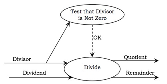
- Constraints: Conditions that must hold true during data processing (represented by braces {}).
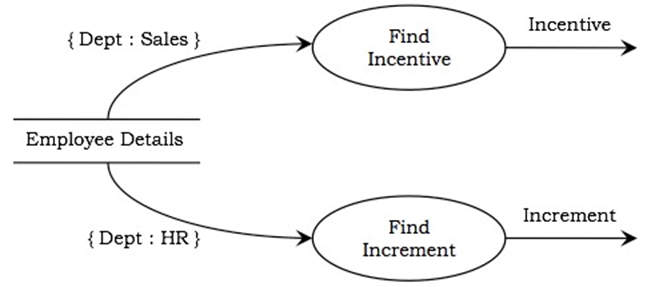
- Control Flows: Boolean values controlling the activation of processes (represented by dotted arrows). A process may be associated with a certain Boolean value and is evaluated only if the value is true,
4. Data Dictionary
Definition: A data dictionary is a centralized repository that contains metadata about the data (i.e database) in the system, including definitions, relationships, sources, usage, and formats.
- A data dictionary contains metadata i.e., data about the database.
- It plays an important role in building a database.
Purpose: To standardize definitions and facilitate consistency and communication among stakeholders.
The data dictionary in general contains information about the following:
- Names of tables and fields in the database
- Constraints on tables in the database
- Physical storage and access methods.
Advantages:
- Provides well-structured database documentation.
- Helps identify redundancy.
- Aids database administrators in management and maintenance.
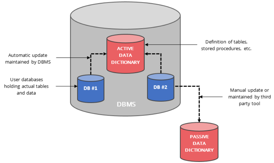
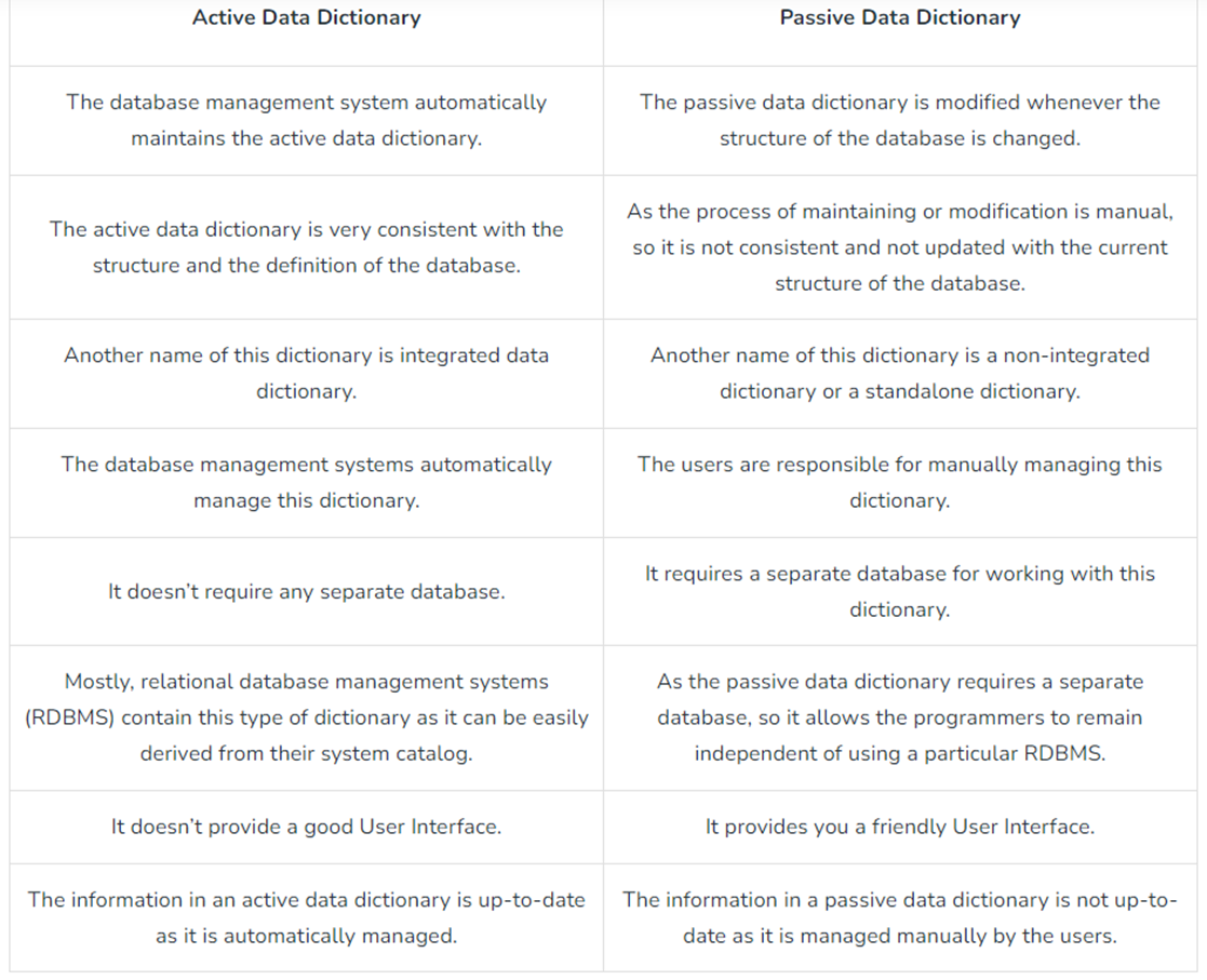
Types:
- Active Data Dictionary:
- An active data dictionary is a type of dictionary that is very consistent and managed automatically by the DBMS.
- Automatically updated by the DBMS.
- Changes in the database are reflected immediately.
- No external maintenance required.
- Cost-efficient and consistent.
- Passive Data Dictionary:
- Maintained manually or through external tools.
- High maintenance cost.
- Prone to becoming outdated.
- Difficult to manage, less reliable than active types.
Four Categories of Data Dictionary:
- Data Flows: Collection of data elements. Data flow is a collection of data elements
- Data Structures: Groups of elements. Usually algebraic notations
- Data Elements: Basic unit of data with specific definition. Data elements definitions describe a data type.
- Data Stores: Data stores are created for each different data entity being stored.
✅ 1. Class Model
A class model is a conceptual representation that describes the structure and behavior of objects within a software system. It defines:
- the objects to be manipulated,
- the attributes and operations associated with them,
- the relationships among these objects,
- and the collaborations that take place between the classes.
✅ 2. Data Modeling
Data modeling is the process of analyzing data objects without considering the processes acting upon them. It focuses on:
- independent data objects,
- their structure and characteristics,
- the relationships among them,
- and the customer's level of abstraction.
It creates a conceptual view of data that reflects how the end-users perceive it.
✅ 3. Data Object
A data object is a representation of any composite information required by the software. It can be:
- an external entity (e.g., user, sensor),
- a thing (e.g., report, document),
- an event (e.g., alarm),
- a role (e.g., administrator),
- a location (e.g., warehouse),
- or a structure (e.g., file or table).
A data object only encapsulates data — it does not define operations or behaviors.
✅ 4. Attributes
Attributes are descriptors or properties that define the characteristics of a data object.
Example:
- Object:
Automobile
- Attributes:
make,model,price,bodyType,color
✅ 5. Relationship
A relationship represents the connection between two or more data objects. It describes how objects are associated or interact with one another.
Example:
- A person owns a car.
- A person is insured to drive a car.
✅ 6. ERD (Entity Relationship Diagram)
An ERD is a graphical notation used to illustrate data objects (entities), their attributes, and the relationships between them. It includes:
- Entity symbols
- Relationship connectors
- Cardinality/multiplicity indicators such as:
- (1,1) → exactly one
- (0,m) → zero or more
✅ 7. Class-Based Modeling
Class-based modeling represents:
- Objects that the system will use or manage
- Operations that act on those objects
- Relationships (including inheritance or aggregation)
- Collaborations between different classes
Key elements include:
- Classes, attributes, operations
- CRC models
- Collaboration diagrams
- Packages
✅ 8. Identifying Analysis Classes
To identify candidate classes from requirements:
- Perform a grammatical parse of scenarios (underline all nouns)
- Each noun may represent a potential class
- Determine whether the noun belongs to:
- Solution space (used in implementation)
- Problem space (used in description only)
✅ 9. Manifestations of Analysis Classes
Analysis classes may take the form of:
| Type | Example |
| External Entities | Users, hardware devices |
| Things | Reports, signals, documents |
| Occurrences/Events | Transactions, triggers |
| Roles | Manager, customer, admin |
| Organizational Units | Department, team |
| Places | Factory floor, loading dock |
| Structures | Sensor, vehicle, table |
✅ 10. Criteria for Potential Classes
| Criterion | Description |
| Retained Information | The class must retain data necessary for system operation |
| Needed Services | It must support relevant operations (methods) |
| Multiple Attributes | Must have more than one meaningful attribute |
| Common Attributes | All instances share the same set of attributes |
| Common Operations | Similar operations applicable to all instances |
| Essential Requirements | Essential for communication between system and external entities |
✅ 11. Defining Attributes
Attributes are assigned depending on the context of the class in the system.
Example:
- For a Sports Management System:
name,battingAverage,fieldingPercentage
- For a Pension System:
salary,pensionOption,vestingStatus
✅ 12. Defining Operations
Operations represent the behavior of a class. They are identified by parsing verbs from the requirements.
Four Categories:
- Data Manipulation (add, update, delete)
- Computation (calculate salary, total marks)
- Inquiry (check status)
- Event Monitoring (detect threshold breach, motion detection)
✅ 13. CRC Models (Class-Responsibility-Collaborator)
CRC (Class-Responsibility-Collaborator) modeling uses index cards to document:
- Class name
- Responsibilities (left side)
- Collaborators (right side)
This method helps visualize how classes interact and what responsibilities they carry.
✅ 14. Class Types
| Type | Purpose |
| Entity Class | Represents core domain concepts (e.g., Sensor, FloorPlan) |
| Boundary Class | Manages user interface (e.g., forms, reports) |
| Controller Class | Coordinates operations, workflows, and communication between classes |
✅ 15. Responsibilities
- Distribute responsibilities logically among classes
- Keep related data and behavior together
- Avoid scattering related data across multiple classes
- Responsibilities should be general and reusable
- Shared where needed across related classes
✅ 16. Collaborations
Classes fulfill their responsibilities either:
- Independently (using their own methods)
- Collaboratively (interacting with other classes)
Types of relationships:
- Is-part-of
- Has-knowledge-of
- Depends-upon
✅ 17. Associations and Dependencies
| Term | Explanation |
| Association | A structural relationship (e.g., student enrolls in courses) |
| Dependency | A situation where one class relies on another to perform a task or supply data |
✅ 18. Multiplicity
Specifies the number of instances that can be involved in a relationship:
- (1,1) → Exactly one
- (0,m) → Zero or many
- (1,n) → At least one
✅ 19. Analysis Packages
To organize a large model, related classes and use-cases are grouped into packages.
Visibility symbols:
+→ Public (accessible everywhere)
- → Private (not accessible outside the package)
#→ Protected (accessible only to related packages)
✅ 20. Reviewing the CRC Model
During review:
- CRC cards are distributed among team members
- Collaborating classes are held by different people
- A scenario is read aloud and tokens passed to relevant class holders
- Each describes the class’s responsibilities
- If responsibilities or collaborations are missing, they are revised or added
Project Planning
Project Planning is an organized process from requirements gathering to testing and support.
Software Project Manager
Managing People
- Act as a Project Leader
- Contact with stakeholders
- Managing human resources
Managing Projects
- Defining and setting up project scope
- Managing project management activities
- Monitoring progress and performance
- Risk analysis
- Take necessary step to avoid or come out of problems
Project Planning Process
- Identify Stakeholders Need: meet the expectations of stakeholders
- Identify Project Objectives: specific, measurable, achievable objectives
- Deliverable and due dates: fixed date and time that an objective is due, deliverables = products, service or result
- Project Schedules: project start and end date
- Provide Roles and Responsibilities: effective communication, who is involved and their task, understand expected objective
- Identify Project budget: anticipating budget cost, monitoring budget
- Identify Communication Plan: effective communicate with client, team and others
- Provide tracking and management: deliver project on time and organize task, track productivity and growth of project
Resource used in Project Management
- Human
- Reusable Components
- Hardware and Software tools
Project Scope Management
Scope = set of deliverables or features of a project
Scope management = creates boundaries of the project by clearly defining what would be done and what not
Steps
- Plan Scope Managements : documentarian and guidelines of project scope, product scope, project life, how to define, validate and control.
- Collect Requirements: collect requirements from all stakeholders
- Defining Scope: identifying project objectives, goals, tasks, budget, resources, schedule, expectation
- Create WBS: Work Breakdown Structure = subdividing project deliverables into smaller units, break down into phases, including priority task
- Validate Scope: focuses on mainly customer acceptance, customer gives feedback
- Control Scope: monitoring the status of the project and managing changes
WBS : Work Breakdown Structure
A top-down hierarchical decomposition of the total project scope into manageable sections.
Working of WBS Steps
- Project managers decide project name at top
- Project managers identifies the main deliverables of the project
- These main deliverables are broke down into smaller higher-level tasks
- Process is done recursively to produce much smaller independent task
- Choose task owner. they need to get the job down
Components
- WBS Dictionary: Document that defines the various wbs element
- WBS levels: determines the hierarchy level of a wbs elemet
- Task : main deliverable tasks
- Sub tasks: devided tasks
- Control account : group work packages and measure their status
- project deliverables: desired outcome of project tasks and work package
Project Scheduling
Definition: The process of converting a project plan into an operating timetable.
Project scheduling is responsible activity of project manager.
Process:
- Identify all the functins required
- \Break down large function into smaller activites , wbs
- Determine the dependency among various activities
- Allocate resources to activities
- Assign people to conduct different activities
- Plan the beginning and ending dates for different activities
- Create activity network and bar or gratt chart
Techniques:
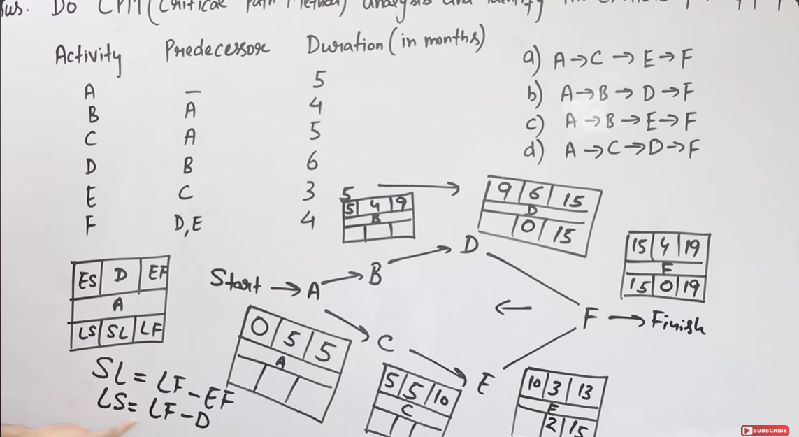
- CPM :
The Critical Path Method (CPM), also known as Critical Path Analysis (CPA), is a project management technique that identifies the longest sequence of tasks (the critical path) that must be completed on time to finish the project, highlighting tasks that directly impact the project's timeline.