Q/A Microwave
| Created by | Borhan |
|---|---|
| Last edited time | |
| Tag | Year 3 Term 2 |
- What is microwave? Why microwave is called transverse electromagnetic wave?
- Mention the frequency range allocated for microwave communication.
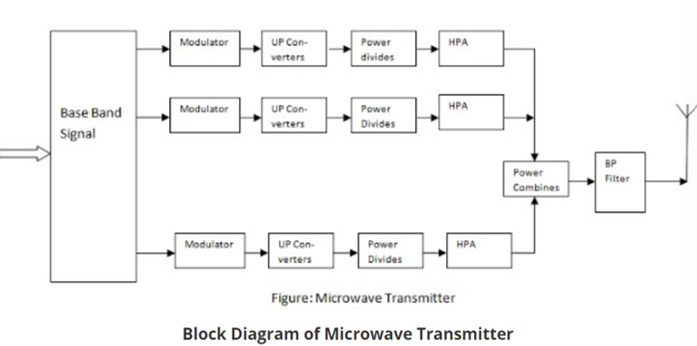
- Draw the block diagram of microwave transmitter.
- Write the frequency range for C-band and K-band.
Solutions:
Microwave is a line-of-sight wireless communication technology that uses high frequency beams of radio waves to provide high speed wireless connection that can send and receive voice, video and data information.
Microwaves are called transverse electromagnetic waves because the electric and magnetic fields that make up the wave oscillate perpendicular to each other and to the direction the wave travels.
Wavelength : as long as 1 meter as short as 1 millimeter
Frequency: 300MHz to 300 GHz
Microwave frequency bands are designated by specific letters
| Letter | GHz |
|---|---|
| L | 1-2 |
| S | 2-4 |
| C | 4-8 |
| X | 8-12 |
| Ku | 12-18 |
| K | 18-26.5 |
| Ka | 26.5-40 |
| Q | 30-50 |
| U | 40-60 |
| V | 50-75 |
| E | 60-90 |
| W | 75-110 |
| F | 90-140 |
| D | 110-170 |
- Why Antenna is called transducer? Define Aperture efficiencу.
- What is directivity? How can we calculate the directivity?
- Define i) VSWR ii) Directivity iii) Effective aperture iv) Beam width
- What is VSWR? How to calculate VSWR
- A transmission line having 50 impedance is terminated in a load of (40+j30) . Calculate VSWR
- An antenna that radiates equally in all directions would have effectively zero directionality. What would be its gain (both normal and decibel values).
- "Beam width is the aperture angle from where most of the power is radiated"-Explain.
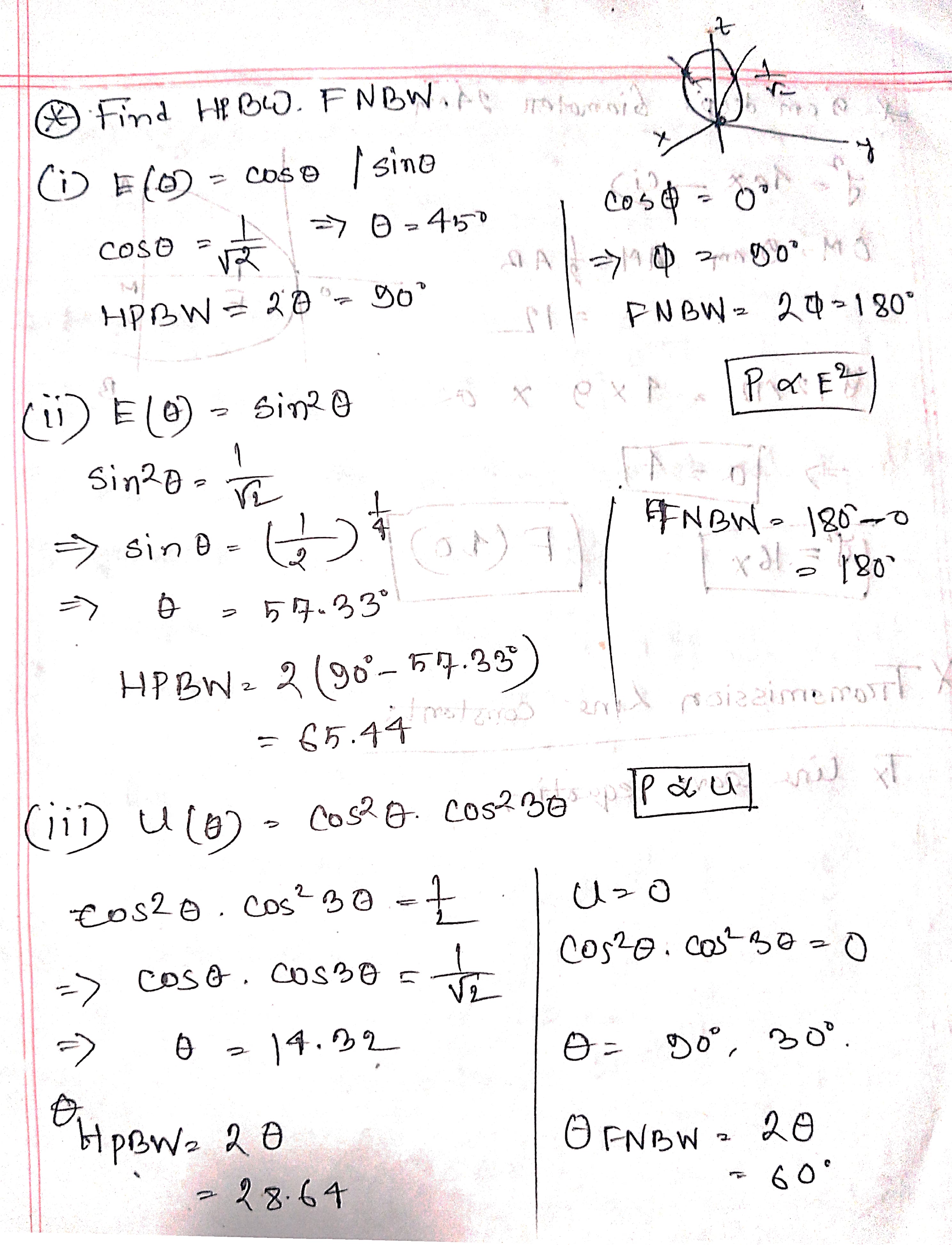
- Define HPBW and FNBW.
- For a given antenna, electric field is E(9) = Sin9. Calculate HPBW and FNBW.
- What is Antenna Efficiency? How to calculate it?
- Write the relationship between antenna length, frequency and wavelength.
- Define ERP with equation.
Solution:
An Antenna is a transducer which converts electrical power into electromagnet waves and vice versa.
An antenna is called a transducer because it converts electrical energy into electromagnetic (EM) waves and vice versa.
Antenna Parameters:
Directivity: The ratio of a maximum radiation intensity of the subject antenna to the radiation intensity of an isotropic antenna, radiating the same total power is called directivity.
The ratio of radiation intensity in a given direction from an antenna to the radiation intensity average overall direction is called directivity.
Directivity :
Gain: Gain describes how much power is transmitted in the direction of peak radiation to that of an isotropic source.
Antenna gain is calculated by multiplying antenna efficiency with directivity of antenna.
An antenna that radiates equally in all directions would have effectively zero directionality, and the directivity of this type of antenna would be 1 (or 0 dB).
An ideal isotropic antenna with 0dB or 1(normal) gain, radiates signal equally in all directions with zero losses .
Aperture efficiencу: Aperture Efficiency is a term used to describe the effectiveness of an antenna in converting electrical energy to it into electromagnetic radiation.
It is the ratio of the effective radiating area to the physical are of the aperture.
Effective aperture (effective area) : The effective aperture parameter describes how much power is captured from a given plane wave.
Let p be the power density of the plane wave (in W/m^2). If P_t represents the power (in Watts) at the antennas terminals available to the antenna's receiver, then:
Antenna Efficiency: It is the ratio of the radiated power of the antenna to the input to the input power by the antenna.
VSWR: VSWR stands for Voltage Standing Wave Ratio, and is also referred to as Standing Wave Ratio (SWR).
VSWR is the ratio of the peak amplitude of a standing wave to the minimum amplitude of a standing wave.
,
A transmission line having 50 impedance is terminated in a load of (40+j30) . Calculate VSWR.
Reflection Coefficient,
Beam width
Beam width is the aperture angle from where most of the power is radiated.
"Beam width is the aperture angle from where most of the power is radiated"-Explain.
Beam width is the angular range (aperture angle) over which the majority of an antenna's power is radiated. It is usually measured between the points where the power drops to half (−3 dB) of its maximum value. This defines the main lobe of the radiation pattern, indicating the direction in which the antenna transmits or receives most effectively.
Half Power Beam Width (HPBW): Half power beam width is the angle in which relative power is more than 50% of the peak power, in the effective radiated field of the antenna.
First Null Beam Width: The angular span between the first pattern nulls adjacent to the main lobe, is called as the First Null Beam Width (FNBW).
Relationship between length, frequency, wavelength
The length of the antenna is inversely proportional to the frequency and directly proportional to the wavelength. The higher the frequency and the shorter the wavelength, the shorter the antenna can be made.
Equivalent Isotropic Radiated Power: The amount of power that an isotropic antenna radiates to produce the peak power density observed in the direction of maximum antenna gain, is called as Equivalent Isotropic Radiated Power.
Effective Radiated Power
If the radiated power is calculated by taking half-wave dipole as the reference, rather than an isotropic antenna, then it can be termed as ERP (Effective Radiated Power).
ERP(dBW)=EIRP(dBW)−2.15dBi
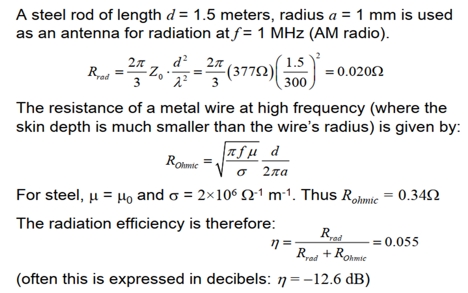
- If the operating frequency is 1 MHz, then calculate the antenna size for a monopole antenna.
- If the operating frequency is 1 MHz, then calculate the antenna size for a dipole antenna.
- If the operating frequency is 1 MHz, then calculate the antenna size.
Solution:
| Antenna Type | Formula | Size at 1 MHz |
|---|---|---|
| Monopole | λ/4 | 300/4=75 |
| Dipole | λ/2 | 300/2=150 |
| Full Wavelength | λ | 300 |
- Explain the half wave dipole antenna.
- What is the impedance of a half wave dipole antenna?
- Define half wave dipole antenna. Write down the features of dipole antenna.
- How do you calculate the size of the dipole antenna in feet? Calculate the size (in feet) of a 30 meter dipole antenna?
- What are the polarization of dipole antenna? Which one-is widely used?
- Draw the 2D radiation pattern of folded dipole antenna.
- What are the advantages and disadvantages of dipole antenna.
- Describe the construction of Yagi-Uda antenna.
Solution:
A dipole antenna is defined as a symmetrical antenna in which the two ends are at equal potential relative to midpoint.
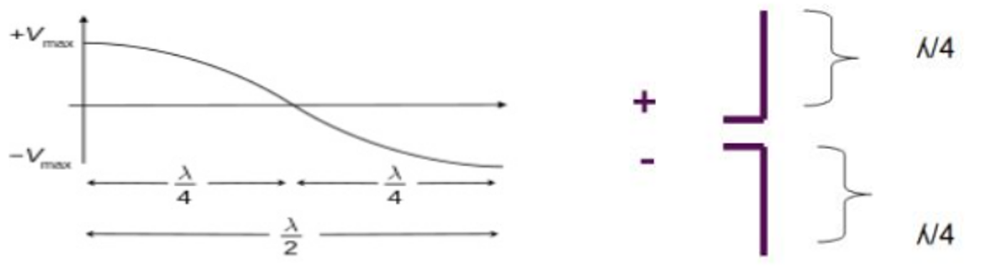
A half wave dipole antenna is the fundamental radio antenna of metal rod thin wire, it has a physical length of half wavelength in free space of the frequency of operation.
Half-wave dipole antenna (Hertz antenna. is the most widely used antenna because of its advantages.
Features of Half wave dipole antenna:
- Dipole antenna with a very thin radius is considered.
- A dipole antenna has two poles where RF current flows.
- It radiates EM signals due to the current and voltage.
- Current is maximum at the center and zero at the ends (sinusoidal).
- Voltage is minimum at the center and maximum at the ends.
- It is usually fed at the center for low impedance (easy to match).
- For very short dipoles, input impedance is mainly capacitive (negative reactance).
- As length increases, both resistance and reactance rise.
- If the length is close to one wavelength, the input impedance becomes infinite.
- At slightly less than half-wavelength, the antenna becomes resonant (no reactance).
- At one wavelength, input impedance becomes very high.
- The half-wave dipole antenna is a special case of the dipole antenna, with a length equal to half the wavelength (λ/2) of the operating frequency.
- The electric current distribution is maximum at the center and zero at the ends.
- It is a center-fed antenna.
- The typical input impedance of a standard half-wave dipole is approximately Zin = 73 + j42.5 Ohms.
- By slightly shortening the dipole to about 0.48λ, the antenna becomes resonant, and the impedance becomes purely real: Zin ≈ 70 Ohms, making it well-matched to transmitters or receivers.
- The directivity of the half-wave dipole is 1.64 (which is equivalent to 2.15 dB).
- The Half Power Beamwidth (HPBW) of the radiation pattern is approximately 78 degrees.
- 3KHz to 300 GHz
(73 Ω resistance and +43 Ω reactance, )
Advantages
- Input impedance is not sensitive.
- Matches well with transmission line impedance.
- Has reasonable length.
- Length of the antenna matches with size and directivity.
Disadvantages
- Not much effective due to single element.
- It can work better only with a combination.
A Yagi-Uda antenna is constructed with a central boom supporting multiple parallel conductive elements: a driven element (usually a half-wave dipole), a reflector (slightly longer), and one or more directors (slightly shorter).
To construct a Yagi-Uda antenna, several components come together to create an efficient and directional antenna for transmitting or receiving electromagnetic signals. The central element is called the "boom," which serves as the framework for mounting all other parts. Connected to the transmission line is the primary element, known as the "driven element," responsible for signal transmission or reception. At the far end of the antenna is the "reflector," a longer element that reflects energy towards the antenna's radiation pattern. In front of the driven element, there are multiple strategically placed "directors" with specific lengths and spacings. These directors assist in directing the antenna's radiation pattern for optimal performance.
- Describe the driven elements for parabolic reflector.
- Explain the principle of operation and application of parabolic reflector and its types
- Where do we use parabolic antenna. Describe different types of common paraboloids.
- Describe the driven elements for parabolic reflector.
Solution:
A parabolic antenna is a high-gain reflector antenna used for radio, television and data communications, and also for radio location (radar) on the UHF and SHF parts of the electromagnetic spectrum .
Why is it used?
At higher microwave frequencies the physical size of the antenna becomes much smaller which in turn reduces the gain and directivity of the antenna.
The desired directivity can be achieved using suitably shaped parabolic reflector behind the main antenna which is known as primary antenna or feed .
Principle Operation
- Focal Reflection: When a wave (e.g., light, sound, or microwaves) originates from the focal point of a parabola, it reflects off the parabolic surface and forms a parallel beam directed along the parabola’s axis.
- Converging Waves: Conversely, parallel incoming waves striking the parabolic surface reflect and converge at the focal point.
Application of parabolic Reflector:
- Telecommunication
- Optics
- Acoustics
- Scientific Research
Types of paraboloid/reflector
| Type | Description | Beam Characteristics | Applications |
|---|---|---|---|
| Truncated Paraboloid | |||
| - Horizontal Truncation | Parabolic in horizontal plane, truncated vertically. | Narrow horizontal beam, spreads vertically. | Surface search radar, detects aircraft at varying altitudes. |
| - Vertical Truncation | Parabolic in vertical plane, truncated horizontally. | Narrow vertical beam, spreads horizontally. | Height-finding systems for precise elevation. |
| Orange-Peel Paraboloid | Segment of circular paraboloid, narrow horizontally, wide vertically. | Wide horizontal beam, narrow vertically. | Height-finding radar equipment. |
| Cylindrical Paraboloid | Curved in one dimension, flat in other; focuses along a line using line source. | Fan-shaped beam, narrow in curved dimension, wide in flat dimension. | Radar systems requiring fan-shaped beams. |
| Corner Reflector | Two flat conductive sheets forming a corner; driven by half-wave radiator. | Simple reflected beam. | Radar and communication systems for wave reflection. |
Types of Microwave feeder/Driven Element
| Type | Description | Advantages | Disadvantages |
|---|---|---|---|
| Axial Feed | Feed antenna is placed at the focus, directly in front of the dish, pointing back. | Simple and common design. | Feed and supports block the beam (efficiency 55–60%). |
| Off-Axis / Offset Feed | Feed is placed to the side of the dish (asymmetrical paraboloid). | No blockage of the beam, better signal reception. | More complex geometry. |
| Cassegrain | Feed located on or behind the dish; uses a convex hyperboloidal secondary reflector to reflect waves back to main dish. | Suitable for bulky or complex feeds; efficiency ~65–70%. | Slightly complex design and alignment. |
| Gregorian | Similar to Cassegrain, but uses a concave (ellipsoidal) secondary reflector. | Very high aperture efficiency (>70%). | Most complex among these; higher cost. |
A parabolic reflector is 9 cm deep and its diameter is 24 cm. How far is its focus from the vertex?
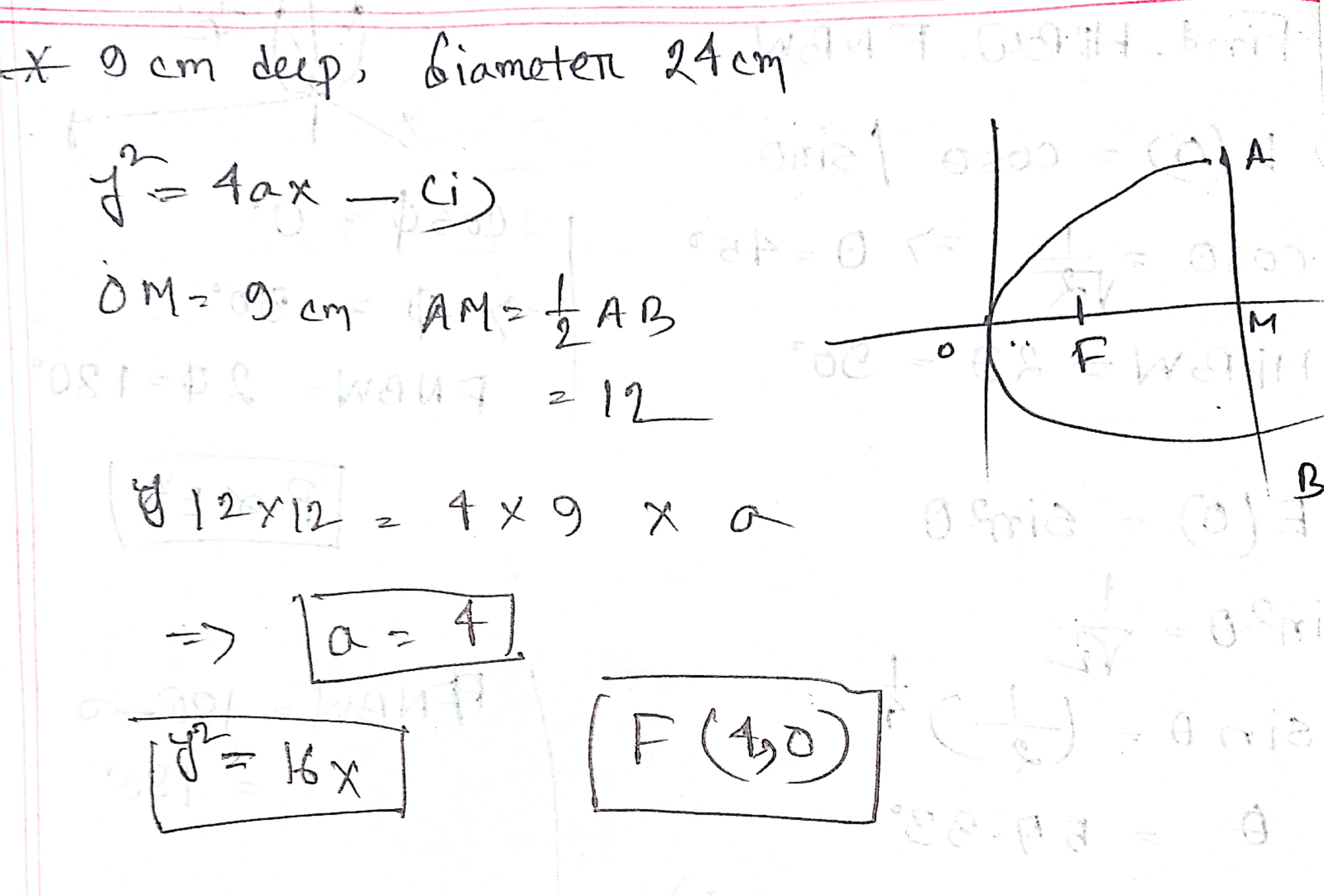
Let the equation of the parabolic shape of the reflector be y² = 4ax. ....(i)
As given, we have OM = 9 cm and AB = 24 cm
⇒ OM = 9 cm and AM = ½ AB = 12 cm.
∴ the coordinates of A are (9, 12).
Since A lies on equation (i), we have:
12² = 4 × a × 9
⇒ a = 4.
∴ the equation of the parabola is y² = 16x.
Its focus is F(a, 0), i.e., F(4, 0).
Hence, the focus is at a distance of 4 cm from the vertex.
- What is radiation pattern? What are the common types of radiation patterns?
- Compare between near and far field pattern.
- What is the simplest antenna design procedure?
Solution
Radiation Patterns are diagrammatical representations of the distribution of radiated energy into space, as a function of direction.
| Radiation Pattern Type | Shape (2D / 3D View) | Description |
|---|---|---|
| Omni-directional Pattern | 3D: Doughnut shape 2D: Figure-of-eight | Radiates equally in all horizontal directions; non-directional. |
| Pencil-beam Pattern | Pencil-shaped, narrow and highly directional | Focused beam in a specific direction; used for long-distance targeting. |
| Fan-beam Pattern | Fan-shaped (broad in one direction, narrow in the other) | Covers a wide area in one plane, narrow in the perpendicular plane. |
| Shaped Beam Pattern | Irregular, custom shape | Beam is tailored for specific coverage; no fixed pattern shape. |
Simplest antenna design procedure:
- Choose Frequency (f): Decide the operating frequency (e.g., 100 MHz).
- Calculate Wavelength (λ)
- Find Antenna Length (L):
- For half-wave dipole: L=λ/2
- For quarter-wave monopole: L=λ/4
- Select Material: Use good conductor (e.g., copper).
- Feed at Center: For dipole, feed in the middle using coaxial cable.
- Test and Adjust: Use antenna analyzer or trim for better signal.
- Calculate the radiation resistance of Hertzian dipole antenna from the total radiated power. If a Hertzian dipole length d= 0.11λ Calculate Rrad?
Solution
The Hertzian dipole is a theoretical dipole antenna that consists of an infinitesimally small current source acting in free-space.
ohm
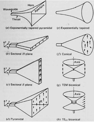
- What are the operational frequencies of horn antenna? Describe different types of horn antenna.
Solution
A Horn antenna may be considered as a flared out wave guide. To improve the radiation efficiency and directivity of the beam, the waveguide should be provided with an extended aperture to make the abrupt discontinuity of the wave into a gradual transformation.
Operational frequencies 300MHz to 30GHz.
| Type of Horn Antenna | Structure / Shape | Flaring Direction | Key Features / Applications |
|---|---|---|---|
| Pyramidal Horn | Truncated pyramid; flaring on both E-plane and H-plane walls of a rectangular waveguide | Both E & H planes | Most common type; used in rectangular waveguides |
| Sectoral E-plane Horn | Flaring in one direction only (Electric field direction) | E-plane only | Narrow beam in E-plane; wider in H-plane |
| Sectoral H-plane Horn | Flaring in one direction only (Magnetic field direction) | H-plane only | Narrow beam in H-plane; wider in E-plane |
| Conical Horn | Circular flare from a circular waveguide | All around (circularly symmetric) | Used with circular waveguides; good for symmetric beam patterns |
| Exponential Horn | Curved sides; flare increases exponentially with length | Smooth exponential flare | Minimum reflection, wide bandwidth; used in satellite antennas and radio telescopes |
- If aperture length (H-plane) 125mm, aperture width (E-plane) 100mm and operating wavelength 30cm for a horn antenna, then calculate the antenna gain in dB.
Transmission Line
- Contrast between transmission lines and waveguides.
| Waveguide | Transmission Line |
|---|---|
| The waveguide is a hollow metallic structure through which electric and magnetic fields are transmitted. | The transmission line is a conductor which is used to carry electrical signal over a long range. |
| It has simple to manufactured. | It has complex to manufactured. |
| In waveguide the power handling is high as compared to transmission line. | In transmission line the power handling is low as compared to waveguide. |
| The Operating modes are TE or TM mode. | The operating mode are TEM or quasi TEM mode. |
| In waveguide high power is transmitted. | In transmission line low power is transmitted. |
| In waveguide the electromagnetic signal is transmitted. | In transmission line the electrical signal is transmitted. |
| The operating frequency is 3 GHZ to 100 GHZ in waveguide. | The operating frequency is up to 18 GHz. |
- Calculate the input impedance of short circuited quarter wavelength lossless transmission line.
- If a transmission line is terminated with a resistance equal to its characteristic impedance- what will happen?
Standing wave ratio will be minimum
, minimum value
VSWR = 1
- A transmission line having 50 impedance is terminated in a load of (40+j30) . Calculate VSWR
VSWR is the ratio of the peak amplitude of a standing wave to the minimum amplitude of a standing wave.
,
A transmission line having 50 impedance is terminated in a load of (40+j30) . Calculate VSWR.
Reflection Coefficient,
- If a transmission line is terminated with a resistance equal to its characteristic impedance then calculate the value of standing wave ratio.
, minimum value
VSWR = 1
- Using solution of transmission line equation, derive characteristics impedance for transmission line.
- What will be propagation constant and characteristic impedance for low-less transmission line?
, f in hertz
- For a 1 volt, 50 MHz signal source with input impedance 75 and load impedance 300 , find i) the characteristics line impedance ii) calculate the transmission line length. If we alter the impedances i.e 75 load and 300 source, is the impedance matches? If yes, explain.
,
Now, since quarter-wave transformers are symmetric, impedance matching is still achieved even when source and load are swapped.
- What type of losses occurs due to impedance mismatch?
Impedance matching in transmission lines is the practice of ensuring the source, transmission line, and load impedances are equal to minimize signal reflections and maximize power transfer
The transmission line, if not terminated with a matched load, occurs in losses. These losses are many types such as attenuation loss, reflection loss, transmission loss, return loss, insertion loss, etc
- A 100 V peak signal at 1 GHz is applied to a transmission line of characteristic impedance 100 Ω, terminated with an antenna of 75 Ω. Calculate incident current and reflected current. Note that the reflection coefficient at the load is .
- If a section of 300 ohm twin lead has a velocity factor of 0.82. Compare the speed of energy transferred with respect to the vacuum.
The speed of energy transfer in the twin lead is approximately 82% of the speed of light in a vacuum.
- If a transmission desirable VSWR line on a transmission line is (i) 0 (ii) 1 (iii) ½ (iv) infinity.
Ans : 1
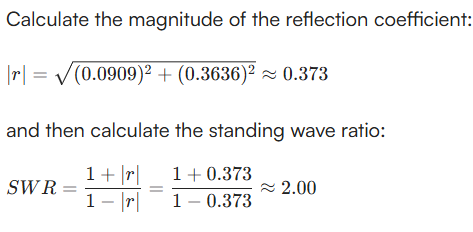
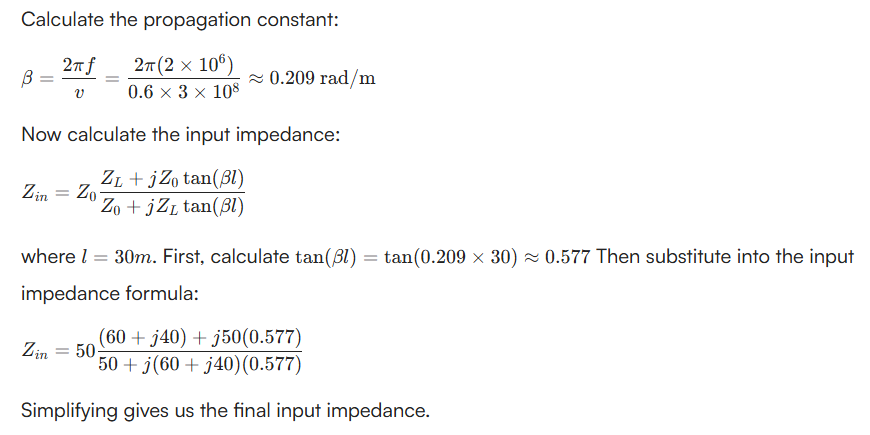
- a. A 30m long lossless transmission line with Zo = 50 operating at 2 MHz is terminated with a load Z = 60 + j40. If v = 0.6C on the line. C represents the velocity of light. Find:
i. The reflection coefficient r
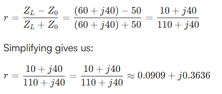
ii. The standing wave ratio
iii. The input impedance
- Define Impedance Matching. Why Impedance Matching are necessary?
Impedance matching in transmission lines is the practice of ensuring the source, transmission line, and load impedances are equal to minimize signal reflections and maximize power transfer
Impedance matching is necessary to maximize power transfer and minimize signal reflections in electrical circuits
Scattering Matrix
It is a square matrix which gives all the combinations of power relationships between the various input and output ports of a Microwave junction. The elements of this matrix are called "Scattering Coefficients" or "Scattering (S) Parameters".
- Write the properties of scattering matrix.
- [S][S] is always a square matrix of order (nxn)
- [S][S] is a symmetric matrix
- [S][S] is a unitary matrix
- The sum of the products of each term of any row or column multiplied by the complex conjugate of the corresponding terms of any other row or column is zero.
- If the electrical distance between some port and the junction is , then the coefficients of involving , will be multiplied by the factor
- [S][S] is always a square matrix of order (nxn)
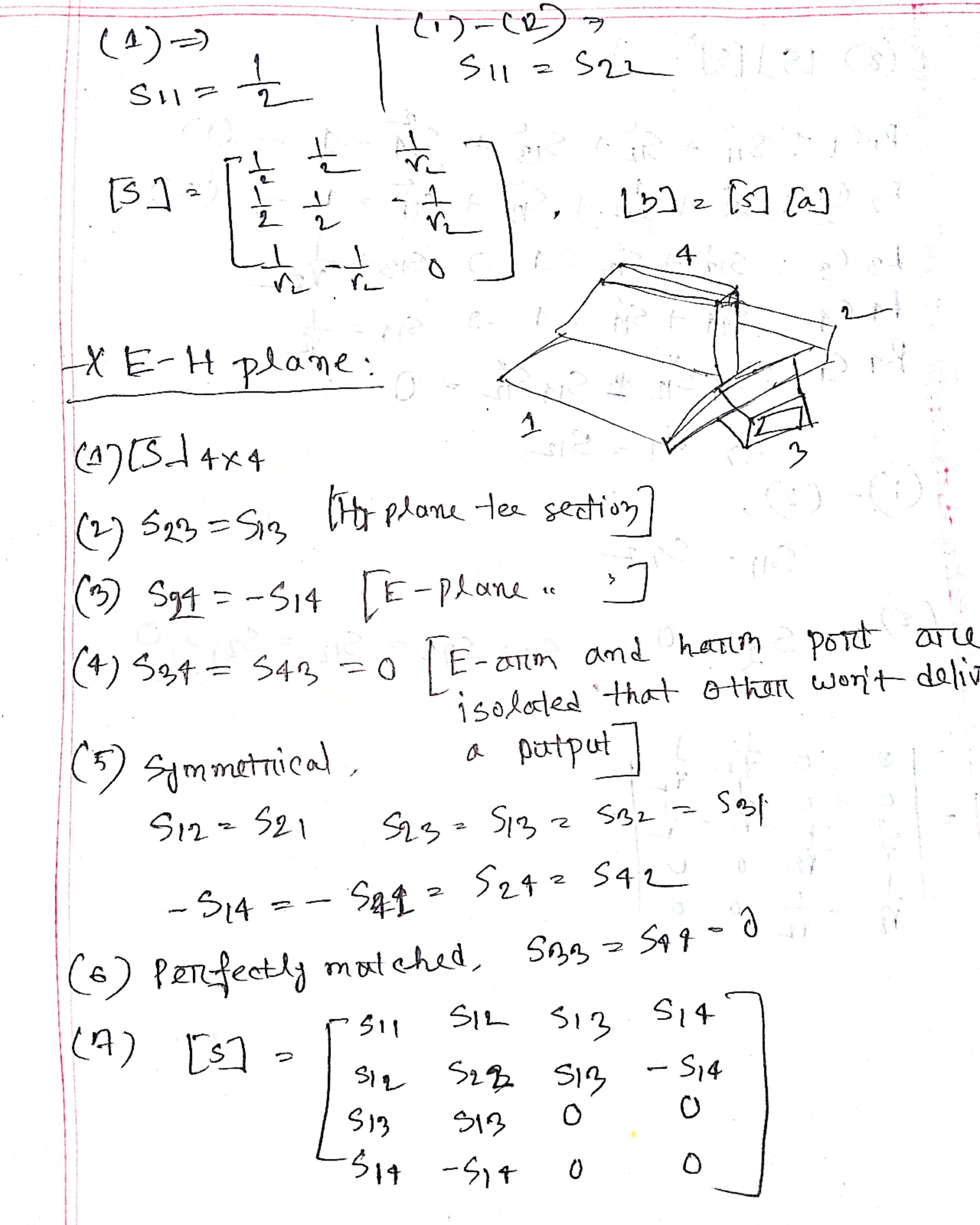
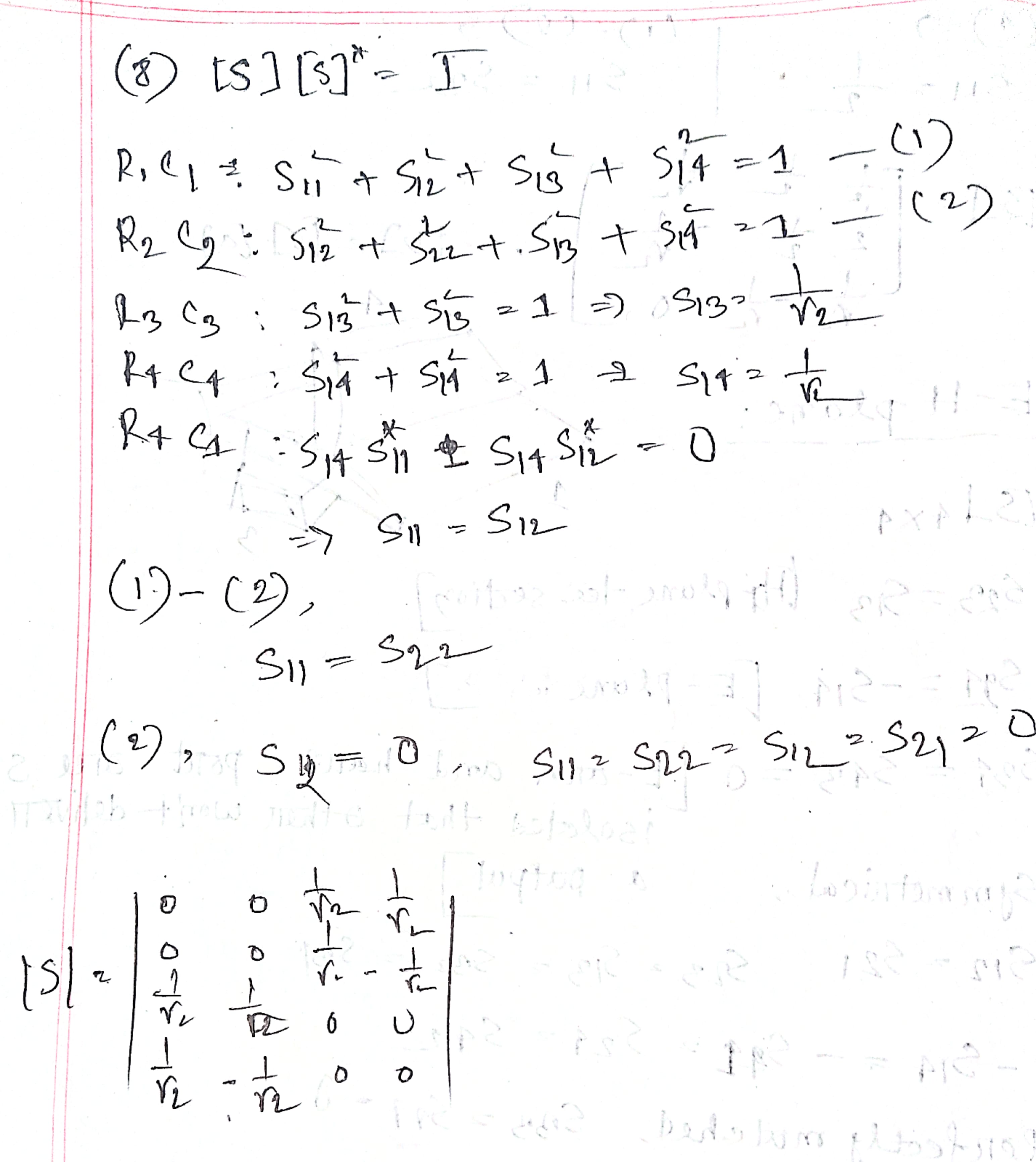
- Compare among E-plane, H-plane and magic Teе.
| Aspect | E-Plane | H-Plane | Magic Tee |
|---|---|---|---|
| Definition | Plane of electric field | Plane of magnetic field | Hybrid junction of E- and H-planes |
| Field Orientation | Electric field | Magnetic field | Combines both fields |
| Structure | Part of waveguide/antenna | Part of waveguide/antenna | Four-port device |
| Radiation Pattern | Vertical (E-field direction) | Horizontal (H-field direction) | N/A (device, not pattern) |
| Isolation | No inherent isolation | No inherent isolation | Yes, between specific ports |
| Power Division | Not applicable | Not applicable | Equal or controlled split |
| Applications | Antenna pattern analysis | Antenna pattern analysis | Power splitting, mixing |
| Phase Behavior | Depends on antenna design | Depends on antenna design | 180° phase difference possible |
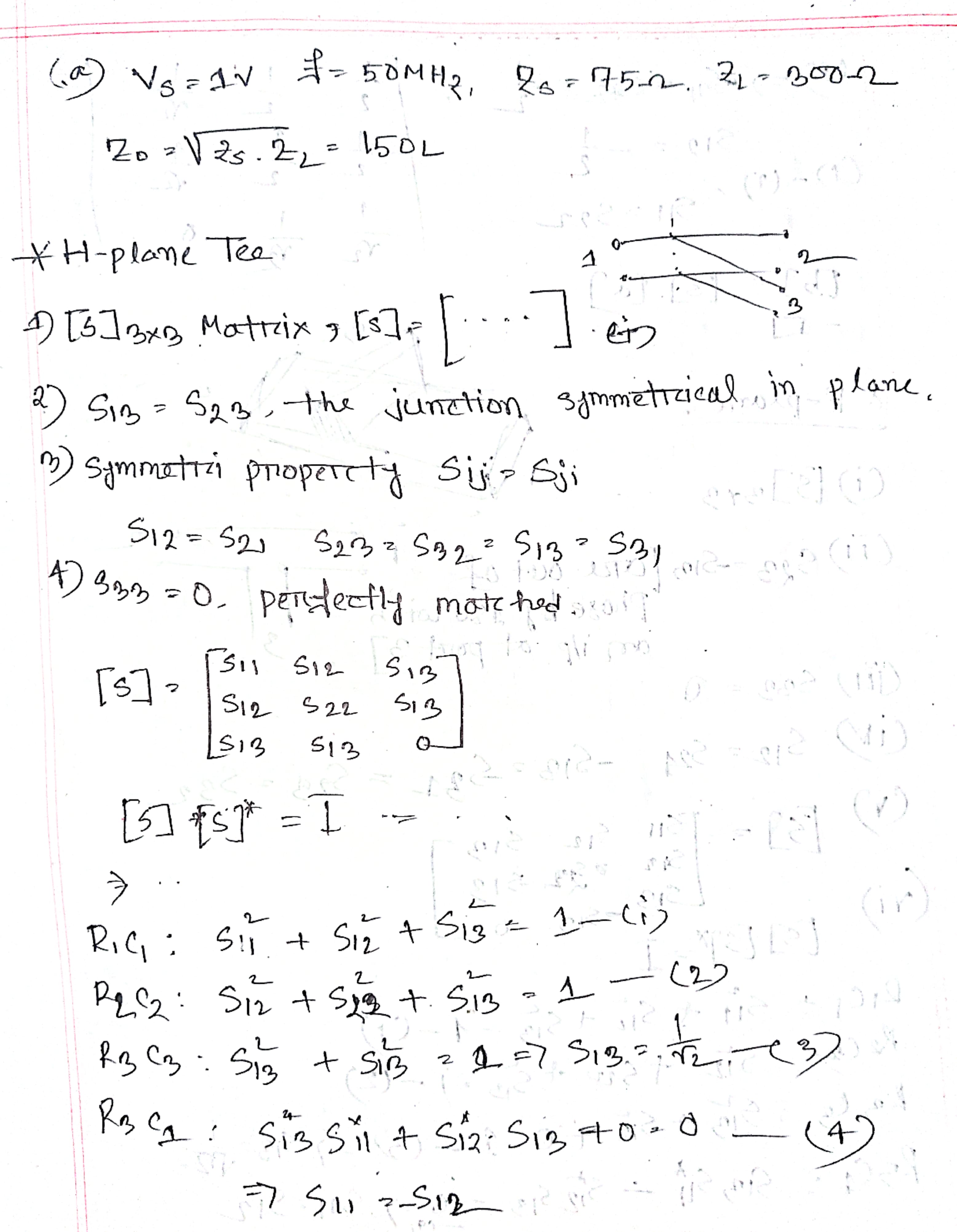
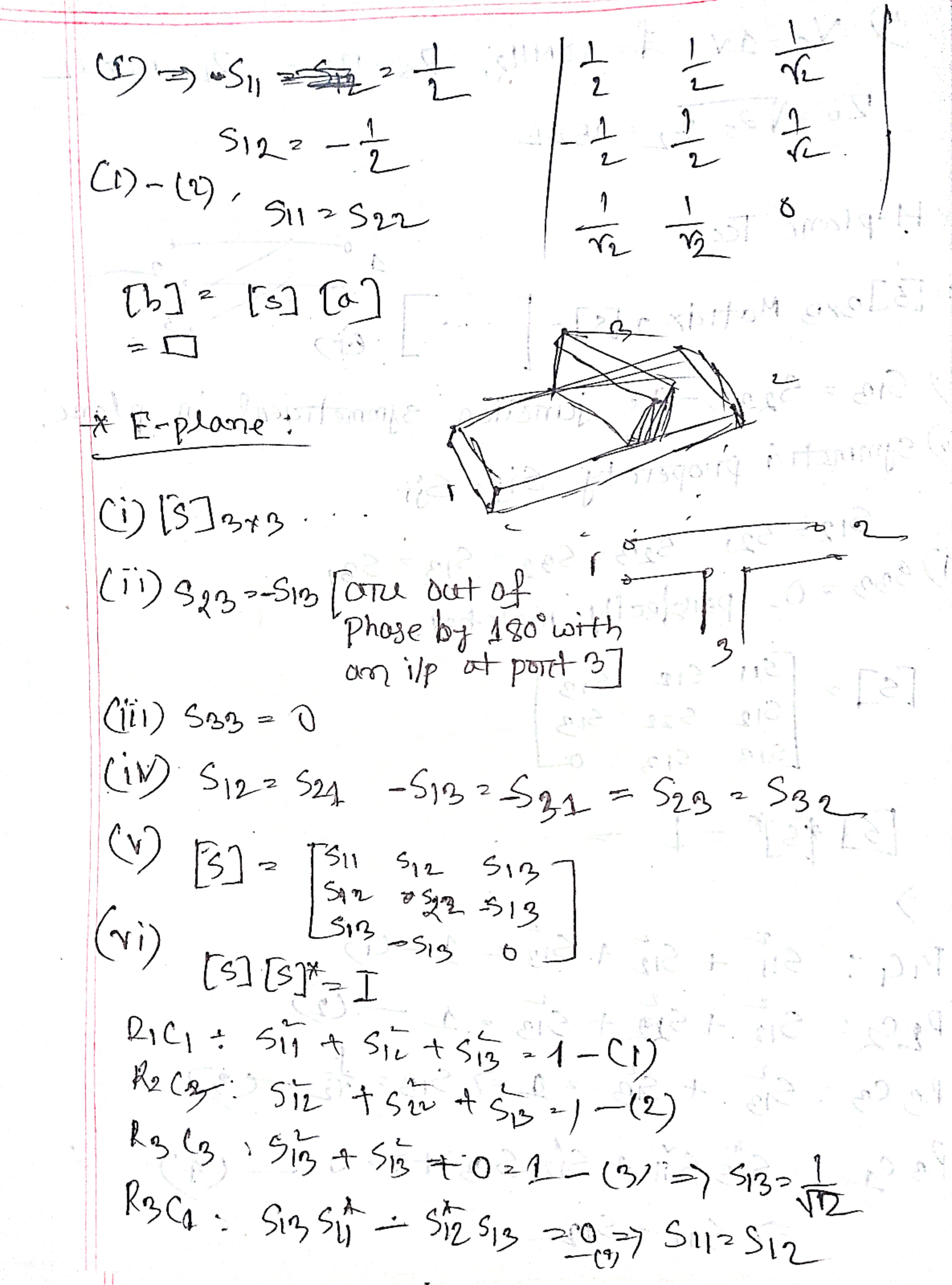
- Find the scattering matrix for the H-plane tee.
- What is H-plane Tee? Explain the scattering properties of H-plane Tee with the help of scattering matrix.
An H-Plane Tee junction is formed by attaching a simple waveguide to a rectangular waveguide which already has two ports. The arms of rectangular waveguides make two ports called collinear ports i.e., Port1 and Port2, while the new one, Port3 is called as Side arm or H-arm. This H-plane Tee is also called as Shunt Tee.
The H-plane (Magnetic plane) is the plane containing the magnetic field vector (H-field) and the direction of propagation.
- What is directional coupler? Write down the properties of an ideal directional coupler.
- Write the properties of ideal directional coupler.
Directional coupler is a four-port device where Port 1 is the incident port, Port 2 is the through port (because it connects via a straight line). Port 4 is the coupled port, and Port 3 is the isolated port.
Properties:
- All the terminations are matched to the ports.
- Demo for below: When the power travels from port 1 to port 2, some portion of it gets coupled to port 4 but not to port 3.
| Travels | Coupled | not coupled |
|---|---|---|
| 1 → 2 | 4 | 3 |
| 2 → 1 | 3 | 4 |
| Incident through port 3 | 2 | 1 |
| Incident through port 4 | 1 | 2 |
- Port 1 and 3 are decoupled as are port 2 and port 4.
- Ideally, the output of port 3 should be zero. But, practically, a small amount of power called back power is observed at port 3.
- Compare among isolator, circulator and phase shifter.
| Feature | Isolator | Circulator | Phase Shifter |
|---|---|---|---|
| Definition | Allows signal in one direction only, blocks reverse | Routes signal from one port to the next port in a circle | Shifts the phase of signal without changing its magnitude |
| Type of Device | Non-reciprocal 2-port device | Non-reciprocal 3 or 4-port device | Reciprocal 2-port device |
| Main Purpose | Protects devices from reflected signals | Routes signals between ports in a defined sequence | Changes the phase angle of a signal |
| Working Principle | Uses Faraday rotation | Uses Y-junction with magnetized ferrite | Uses delay lines or varactors |
| Signal Flow | Port A → Port B only (blocks B → A) | Port 1 → 2, 2 → 3, 3 → 1 (or circular path) | Same signal goes through, but with phase shifted |
| Ports | 2 (3rd port used for termination) | Typically 3 or 4 | 2 |
| Insertion Loss | ~2 dB | ~0.5 – 1.5 dB | Ideally low in all phase states |
| Key Property | Blocks unwanted reflections | Allows directional signal routing | Provides variable or fixed phase shift |
| Reciprocal? | No | No | Yes |
| Common Use | Between source and load to block reflected power | In radar or duplex communication systems | In phased arrays, beam steering, RF control systems |
Radar
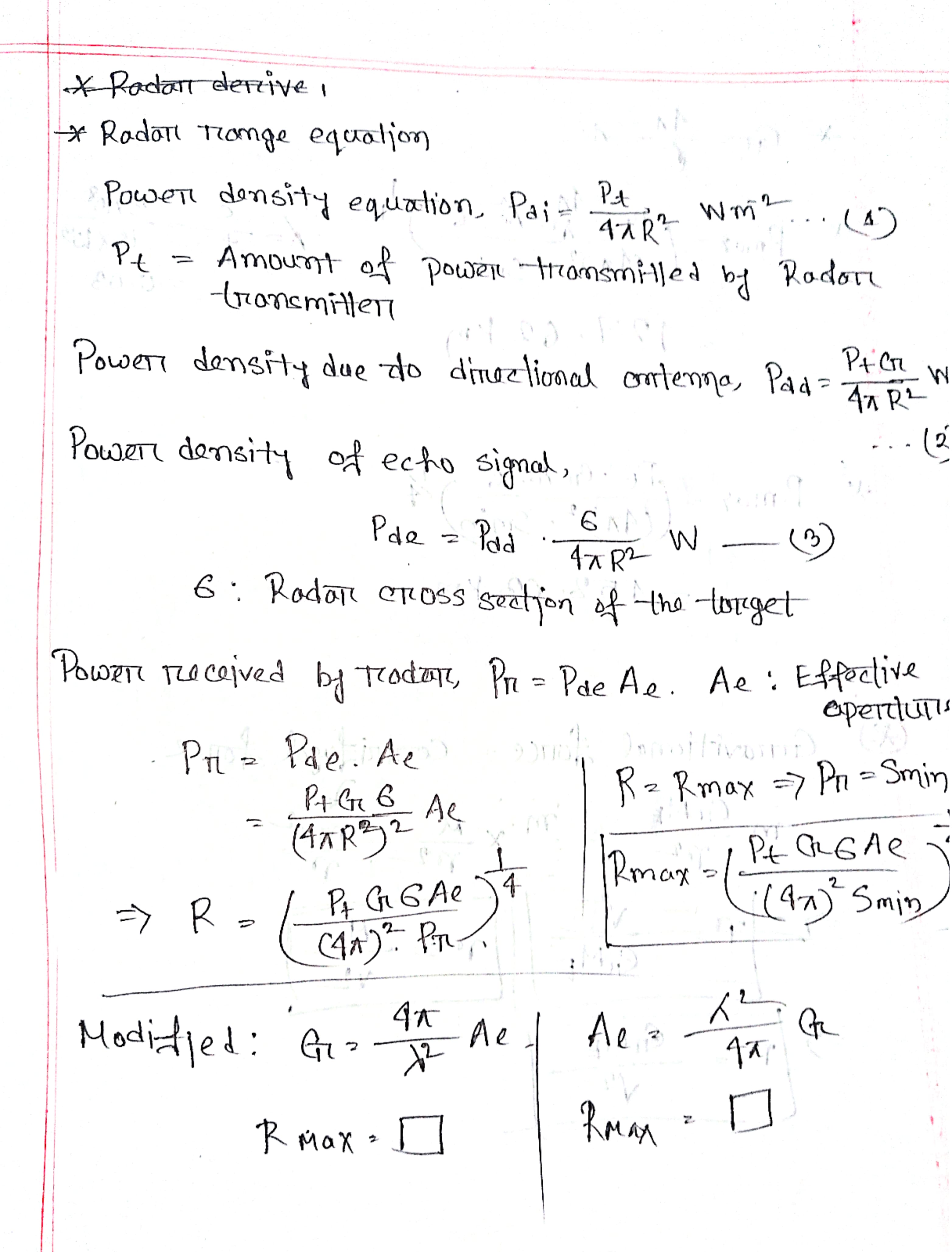
- What is RADAR? Why it is necessary? Derive radar range equation.
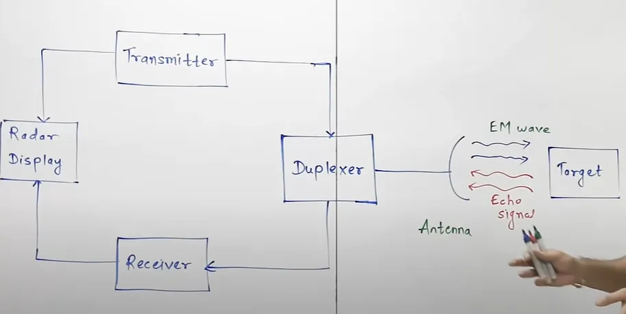
Radar stands for Radio Detection and Ranging System. It detects location and distance of objects using electromagnetic energy. It is basically an electromagnetic system used to detect the location and distance of an object from the point where the RADAR is placed.
Operating range: UHF and microwave frequencies (400 MHz to 40 GHz).
- What is RADAR? Write down the functions of Radar?
- Purpose : Detect, track, locate and identify object
- Capabilities: Determines distance. velocity, shape, size
- Comparison with other sensors: Superior for detecting faraway targets
- Draw RADAR block diagram.
- Describe the working procedure of a moving target indicator radar system..
1. Pulse Transmission
The radar system transmits a train of short radio frequency (RF) pulses toward the surveillance area.
2. Echo Reception
Echo signals are received from both stationary and moving objects after reflecting off targets.
3. Doppler Shift Detection
Moving targets introduce a Doppler shift (change in frequency) in the received signal, which is a key indicator of motion.
4. Phase Comparison
The radar compares the phase of echo signals from successive pulses to detect whether a target has moved between transmissions.
5. Clutter Rejection
Using delay lines or filters, the radar cancels out echoes from stationary objects (like buildings or trees), known as clutter.
6. Output Signal Extraction
After filtering, only the signals from moving targets remain and are processed further.
7. Display
The radar display shows only the moving targets, while stationary objects are suppressed, providing a clear view of moving objects.
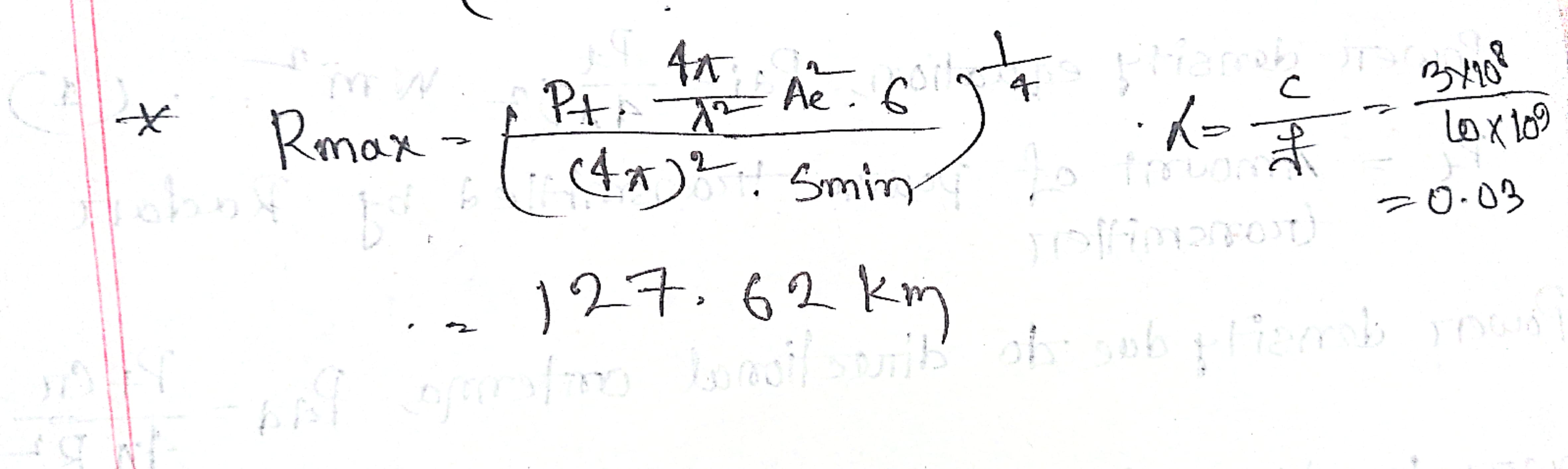
- Calculate the maximum range of Radar for the following specifications. Operating frequency f=10GHZ, peak power transmitted by the Radar 400KW, effective aperture for the receiving antenna A=5m², Radar cross-section of the target σ=30m², power of minimum detectable signal Smin=10^-10°W.
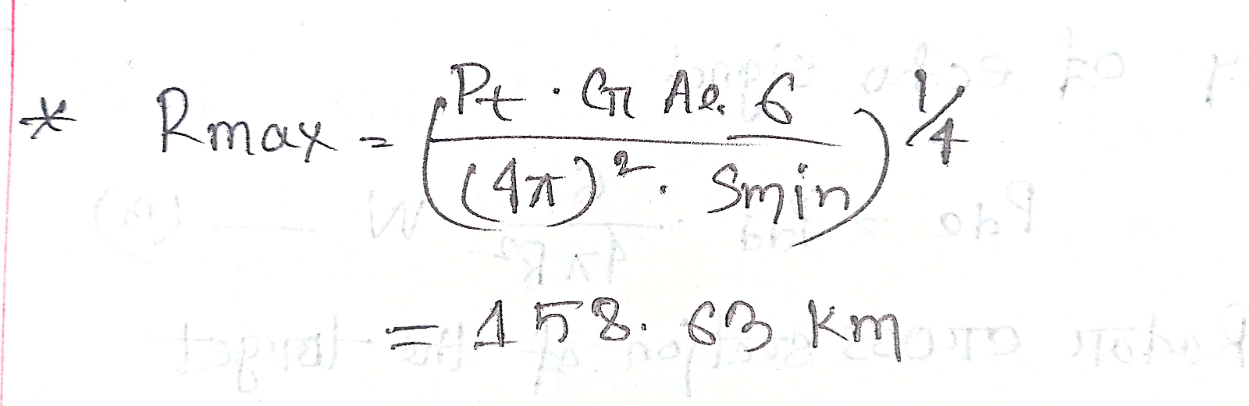
- Calculate the maximum range of the radar when power transmitted by the radar is 250KW, transmitting antenna gain is 4000, effective aperture of the receiving antenna is 4 m², radar cross section of the target is 25 m² and power of the minimum detectable signal is 10^-12 W.
- Discuss how the target is tracked using any one of the angular tracking methods.
[ Extra : Radar, which is used to track the path of one or more targets is known as Tracking Radar.
The pencil beams of Radar Antenna perform tracking in angle. The axis of Radar Antenna is considered as the reference direction. If the direction of the target and reference direction is not same, then there will be angular error, which is nothing but the difference between the two directions. ]
- Sequential Lobing
- Antenna beams are switched alternately between two directions (beam positions) to track a target.
- Radar alternates beam between Position 1 and Position 2.
- Compares received signal strength from both positions.
- Difference in signal strength indicates direction and magnitude of angular error.
- Conical Scanning
- Antenna beam continuously rotates around the boresight axis to track a target.
- The rotating beam traces a cone-shaped path (hence "conical").
- This rotation causes the echo signal to be modulated at the same frequency as the beam rotation.
- The amplitude of the modulation depends on how far the target is from the beam center.
Satellite
A communication satellite is an orbiting artificial earth satellite that receives a communications signal from a transmitting ground station, amplifies and possibly processes it, then transmits it back to the earth for reception by one or more receiving ground stations.
- Define: Eccentricity, vernal equinox, right accession of ascending node, line of nodes. Mention them with appropriate figures.
Eccentricity defines the shape of the satellite orbit. It is the ratio of the distance between the foci of the ellipse to the length of its major axis. For a perfect circle, eccentricity is zero.
The Vernal Equinox is the point where the Sun crosses the Earth’s equatorial plane moving from the southern to the northern hemisphere. It is used as a reference point in the celestial coordinate system.
Right Ascension of Ascending Node is the angle measured from the vernal equinox to the ascending node of the satellite orbit, measured in the equatorial plane.
The line of nodes is the line joining the ascending and descending nodes through the centre of Earth.
- Define: i) look angle ii) sub satellite point iii) apogee and perigee
Look angle is the angle between the direction of the satellite from the Earth station and the local horizontal at the Earth station.
- The angle between local horizontal plane and the plane passing through earth station, satellite and center of earth is called as azimuth angle.
- The angle between vertical plane and line pointing to satellite is known as Elevation angle.
The sub-satellite point is the point on the Earth's surface directly beneath the satellite at any given time.
Apogee is the farthest point of the satellite from the Earth in its orbit.
Perigee is the closest point of the satellite to the Earth in its orbit.
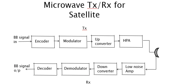
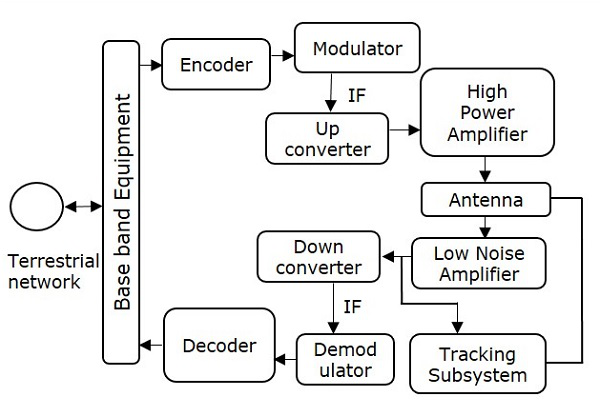
- Write down the functional block diagram of an earth station and explain how signal is processed for transmission and reception.
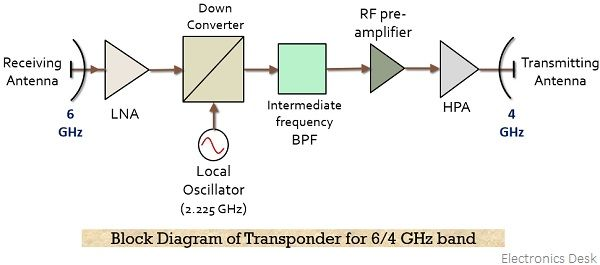
- What is transponder? Explain the block diagram of single conversion transponder.
A transponder is an electronic device that transmits and receives radio signals.
- Explain the block diagram of typical FDMA satellite system.
- Write a short note on SPADE.
- Shortly explain AOC and TTCM subsystem.
| Aspect | AOC Subsystem | TTCM Subsystem |
|---|---|---|
| Full Form | Attitude and Orbit Control | Telemetry, Tracking, Commanding, and Monitoring |
| Main Function | Controls the orientation (attitude) and orbit position of the satellite | Handles communication and control between satellite and Earth station |
| Purpose | Ensures satellite points in correct direction (e.g., antennas towards Earth, solar panels to Sun) | Ensures satellite’s health, position, and commands are transmitted, received, and monitored |
| Methods Used | -Spin stabilization (rotating body)- Three-axis stabilization (using momentum wheels) | - Telemetry (sends sensor data to Earth)- Tracking (finds satellite location)- Commanding (sends control signals) |
| Key Components | - Spinning drum- De-spin mechanism- Momentum wheels for 3-axis control | - Sensors and encoders- RF transmitters for telemetry- Antennas and command receivers |
| Satellite Stability | Keeps satellite stable and correctly oriented in orbit | Keeps satellite communicating and under control from ground |
| Example of Use | Making antennas continuously face Earth despite satellite motion | Sending temperature, pressure data to Earth; commanding thrusters to adjust orbit |
- State and explain Kepler's law. Derive differential equation for the motion of a satellite.
- The orbit of a satellite around the Earth is an ellipse, with the center of mass of the Earth located at one of the two foci of the ellipse.
- A line joining a satellite and the Earth sweeps out equal areas in the orbital plane in equal intervals of time.
- The square of the orbital period of a satellite is directly proportional to the cube of the semi-major axis of its orbit.
;
Distinguish between Active and Passive satellite.
| Aspect | Passive Satellite | Active Satellite |
|---|---|---|
| Definition | A satellite that only reflects signals from Earth without amplification or modification. | A satellite that receives, amplifies, and retransmits signals back to Earth using onboard electronics. |
| Function | Reflects incoming signals from Earth. | Amplifies and retransmits received signals. |
| Power Supply | No onboard power; relies entirely on external transmitted energy. | Contains onboard power sources to operate internal electronics. |
| Earth Station Requirement | Needs high power transmitters and large tracking facilities. | Needs lower power Earth stations due to onboard amplification. |
| Control from Ground | Cannot be controlled once in orbit. | Can be actively controlled and monitored from ground. |
| Signal Strength | Signal weakens significantly (high attenuation) due to long travel path and no amplification. | Signal strength is maintained or enhanced due to onboard amplification (low attenuation). |
| User Access | Open to random users | Controlled access |
| Example | Echo-I (NASA, 1960) | Most modern communication satellites |
| Tracking Facility | Needs large tracking stations | Compact and efficient ground stations possible |
| Amplification | No | Amplifies the received signals |
| Power Generation | Cannot generate or transmit power | Can generate and transmit power |
- Describe the orbit of a satellite.
The path a Satellite follows around a planet is defined as an orbit.
| Aspect | Non-Geostationary Orbit (NGSO) | Geostationary Orbit (GSO) |
|---|---|---|
| Definition | Satellites that orbit the Earth at lower altitudes and do not remain fixed relative to a point on Earth. | A circular orbit directly above the equator where the satellite appears stationary from Earth because it rotates at the same speed as Earth. |
| Orbit Altitude | Low Earth Orbit (LEO) or Medium Earth Orbit (MEO), generally below 35,786 km | Fixed at 35,786 km above the equator |
| Tracking Requirement | Complex tracking needed; satellite moves relative to Earth | Simple tracking; satellite appears fixed in the sky |
| Signal Handover | Requires handover of signal between satellites due to motion | No handover needed; signal from a single satellite is continuous |
| Lifetime & Replacement | Shorter satellite life, requires frequent replacement | Longer life, fewer replacements needed |
| Transmission Delay | Lower delay due to shorter distance | Higher delay (~250 ms) due to long distance |
| Coverage Area | Can provide global or polar coverage | No coverage at poles; best suited for equatorial and mid-latitudes |
| Free Space Loss | Lower, due to closer distance to Earth | Higher, due to larger distance |
| Aspect | GEO (Geostationary Earth Orbit) | MEO (Medium Earth Orbit) | LEO (Low Earth Orbit) |
|---|---|---|---|
| Definition | Satellite appears stationary from Earth; orbits at 36,000 km above equator. | Satellite orbits Earth at 8,000–20,000 km altitude; slower movement than LEO. | Satellite orbits at 500–2,000 km altitude; fast-moving with frequent Earth passes. |
| Orbit Type | Circular orbit above equator, 0° inclination. | Can have varied inclinations; often circular. | Inclined or polar orbits; moves across Earth quickly. |
| Coverage | Covers 1/3 of Earth per satellite; 3 satellites cover almost entire Earth. | Fewer satellites needed than LEO, but more than GEO. | Needs many satellites for full Earth coverage (e.g., 50–200). |
| Latency (Delay) | High (~250 ms); not ideal for real-time data or voice. | Moderate latency; better than GEO but not as good as LEO. | Low latency (~10 ms); ideal for data and voice communications. |
| Footprint | Very large; allows wide area coverage. | Medium footprint; good balance between coverage and resolution. | Small footprint; allows for high frequency reuse like cellular networks. |
| Tracking Requirement | Minimal; appears stationary, so simple ground tracking. | Moderate tracking needed; satellites move slowly relative to Earth. | High tracking required; fast movement requires continuous tracking and handovers. |
| Lifetime | Long (up to 15 years or more). | Moderate lifetime. | Short (5–8 years); affected by atmospheric drag. |
| Use Cases | TV, radio broadcast, weather, global telephone backbone. | GPS, navigation, communication systems. | Mobile communication, remote sensing, Earth observation, internet (e.g., Starlink). |
| Advantages | - Constant view of same area - Ideal for broadcasting - Minimal Doppler shift | - Fewer satellites than LEO - Good regional coverage - Less complex than LEO | - Low delay - Good for mobile & polar regions - Better signal strength due to proximity |
- What are the conditions required for an orbit to Geostationary?
- The satellite should be placed 35,786 kms (approximated to 36,000 kms) above the surface of the earth.
- These satellites must travel in the rotational speed of earth, and in the direction of motion of earth, that is eastward.
- The inclination of satellite with respect to earth must be 0°.
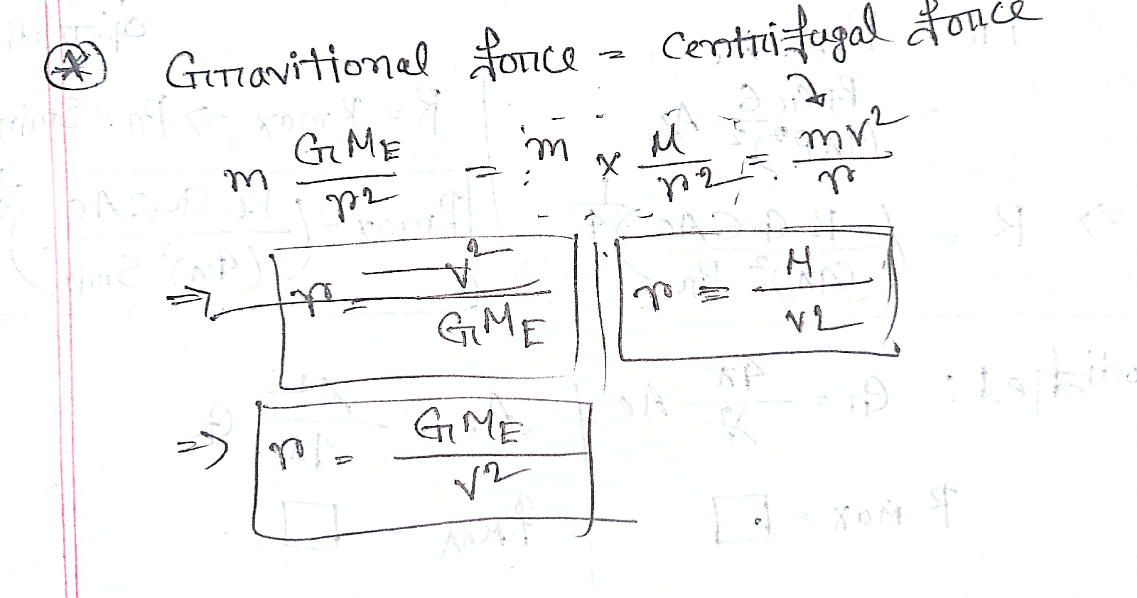
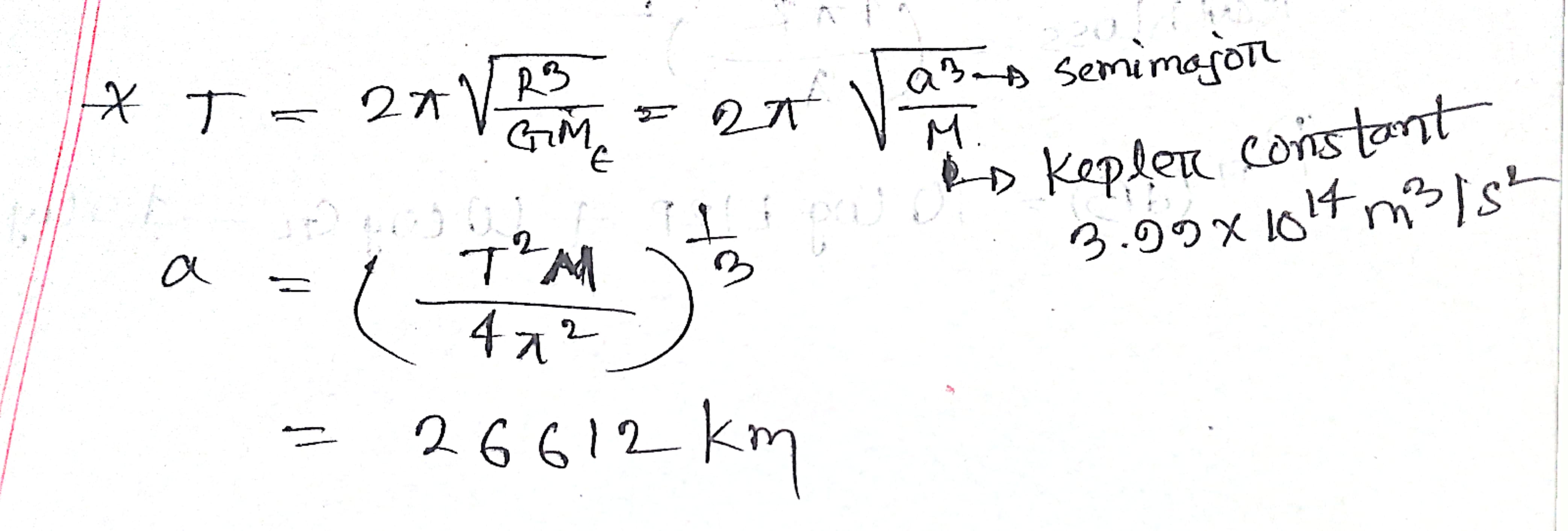
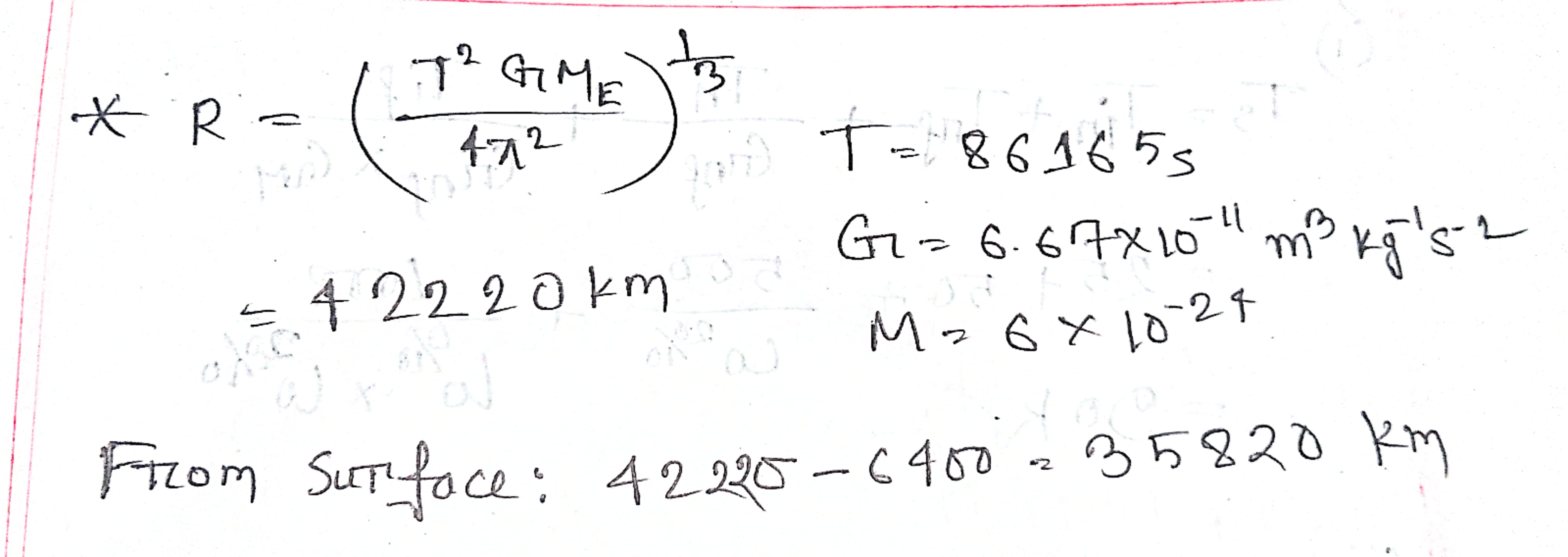
- Derive the standard mathematical equation for the radius of the satellite's orbit r.
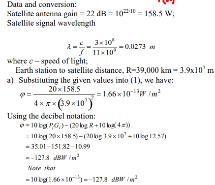
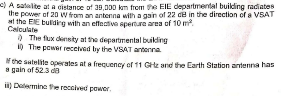
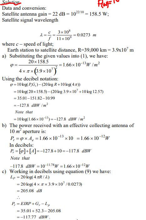
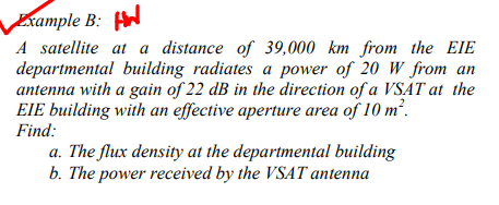
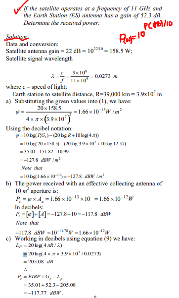
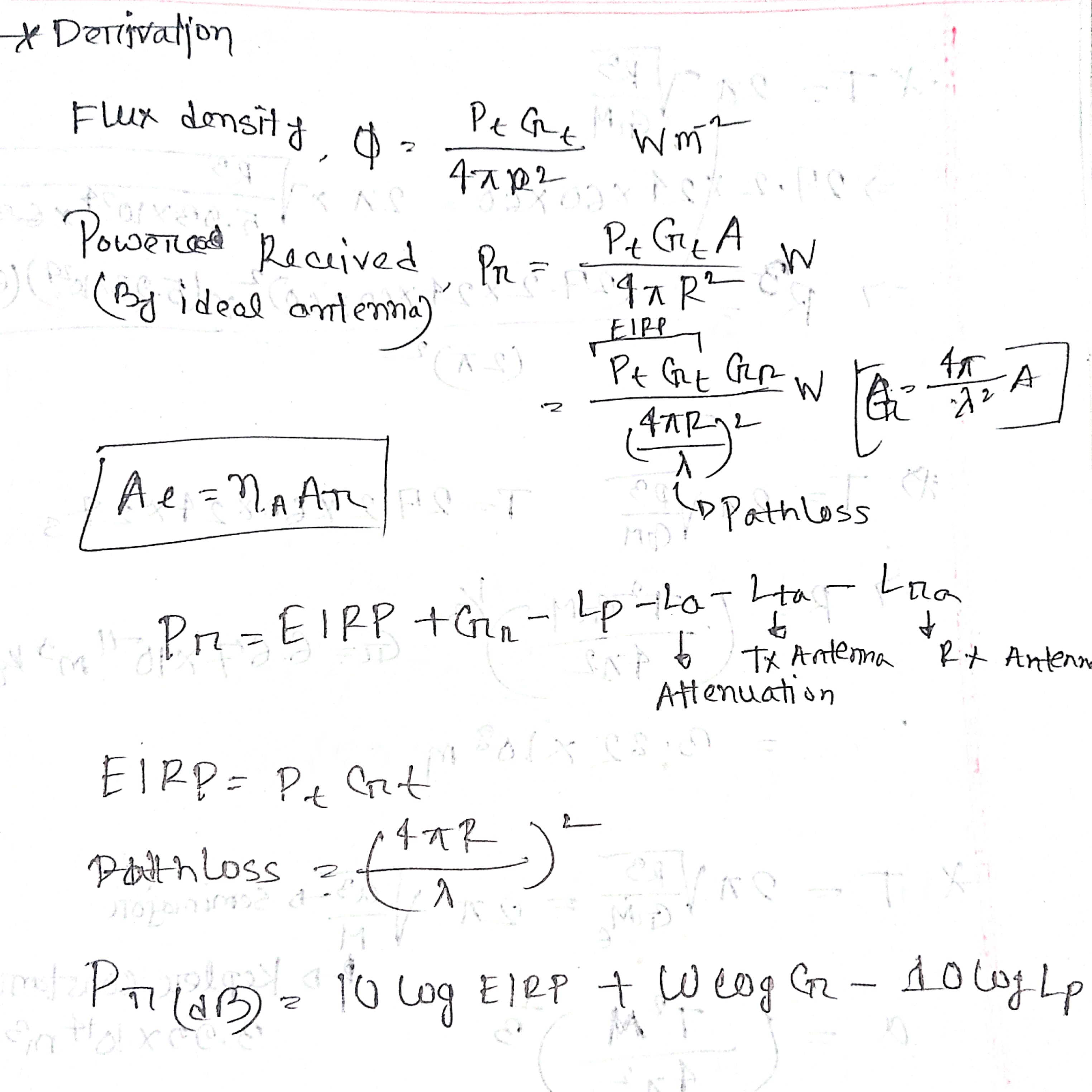
- Write down the equation of power received by an earth station from a satellite transmitter and convert the equation into dBW.
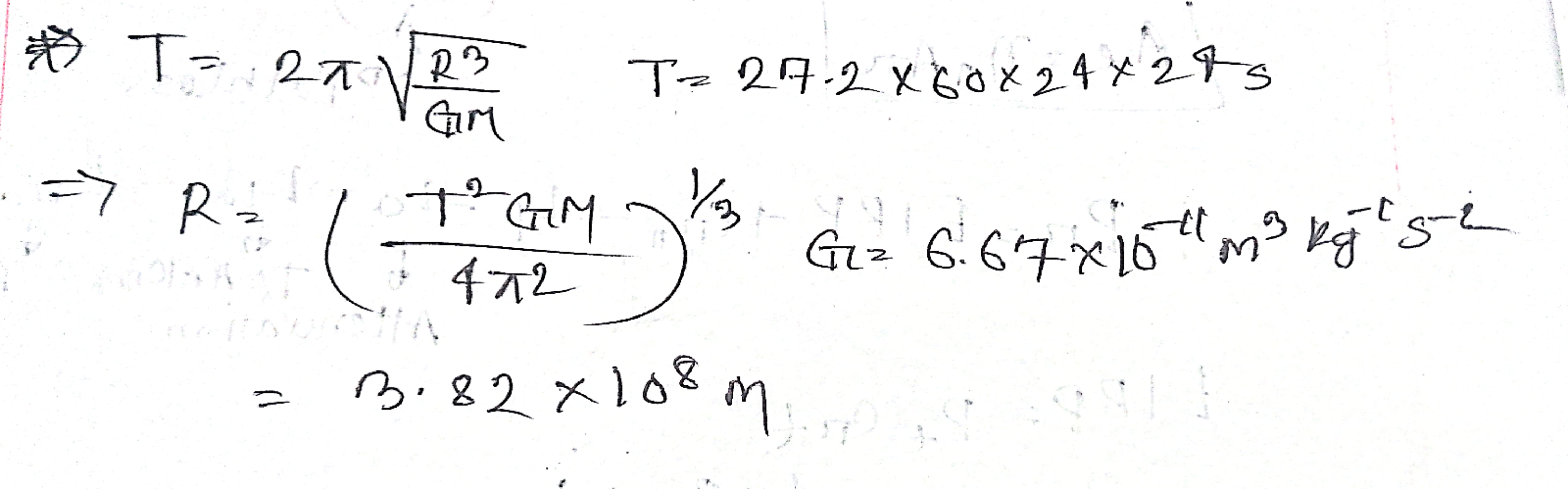
- The period of the moon is 27.2 days. Determine the radius of the moon's orbit and the orbital speed of the moon (Given M_earth =5.98 x 10^24 kg and R_earth =6.37 x 10^6 m).
- A satellite is orbiting in the equatorial plane with a period from perigee to perigee of 12 hours. Given that the eccentricity is 0.002, calculate the semi major axis. The earth's equatorial radius is 6378.1414 Km.
- A satellite downlink at 12 GHz operates with a transmit power of 6 W and an antenna gain of 48.2dB. Calculate the EIRP in dBW
- The orbital period of a Geo stationary satellite is T=23h56min409sec. Calculate the distance of the satellite from earth surface. What will be the linear velocity?
⇒
(c)