The transient response of a system due to initial condition or due to changing inputs cannot be computed by using DTFT but Z.
The Z-transform might exist anywhere in the Z-plane; the DTFT can only exist on the unit circle.
Z transform allows for the discrete time system analysis in the frequency domain. This facilitates the analysis of system characteristics such as stability, causality, linearity and time and frequency response.
Z transform allows the representations of signals and systems in the frequency domain.
It becomes possible to analyze frequency content of signals determine spectral properties, apply filtering and modulation.
Useful for determining the stability of DT system.
It has convolution property that simplifies the analysis of linear time invariant system.
Simplifies mathematical operation.
The Transfer Function
The transfer function H(z) of a DT linear system is defined as the ration of the Z-transform of the output signal Y(z) to the Z-transform of the input signal X(z)
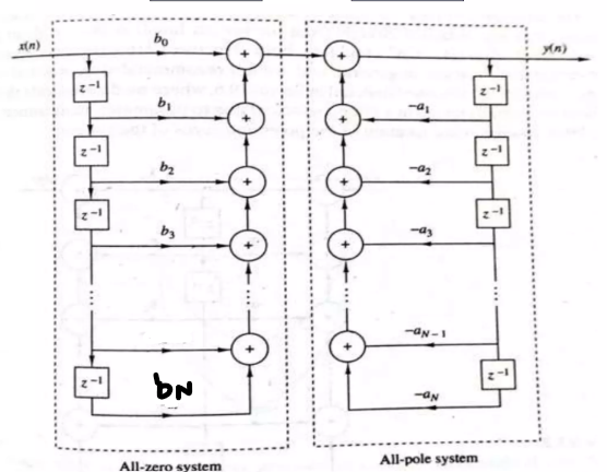
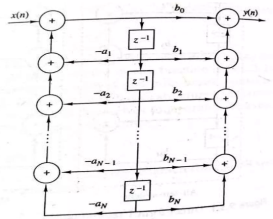
H(z)=X(z)Y(z)=∑m=−∞+−∞amz−m∑n=−∞+−∞bnz−n
=a0+a1z−1+...+anz−nb0+b1z−1+...+bmz−m
Where, b0,b1,... are input coefficient and a0,a1... are output.
if ao=1, then this called the standard form of transfer function.
If we can convert, H(z)=G(z−p1)(z−p2)...(z−pn)(z−z1)(z−z2)...(z−zn)
Then, z1,z2... are called zeros and p1,p2.... are called poles.
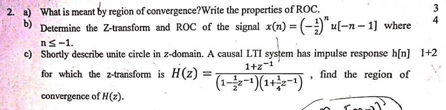
Distinguish between Zeros and Poles
Poles
Zeros
A pole of the transfer function H(z) is value of z that makes the denominator zero.
A zero of the transfer function H(z) is a value of 𝑧 that makes the numerator zero.
Mathematical : H(z) = N(z)/D(z) If D(z) = 0, at z=zp, then H(z) → infinity as z→ zp
Mathematical : H(z) = N(z)/D(z) If N(z) = 0, at z=zs, then H(z) → 0 as z→ zs
Influence system stability and response
Influence frequency response
Poles outside the unit circle indicate instability
Zeros do not affect stability directly
Represented by "X" in the Z-plane
Represented by "O" in the Z-plane
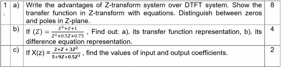
(b)Transfer function representation : X(z)=D(z)N(z)=1+a1z−1+....+anz−nb0+b1z−1+....+bmz−m=a0+a1z−1+....+anz−nb0+b1z−1+....+bmz−m [a0=1 means normalized] .z=ejω
H(z)=1+0.5z−1+0.75z−21+z−1+z−2 [Dividing by z2]
H(ejω)=e2jω+0.5ejω+0.75e2jω+e2ω+1 [Replace z=ejω on given X(z) of the question]
Difference equation representation : Transfer function → Inverse Z-transform → y(n)
Idea : X(z)=D(z)N(z)=a0+a1z−1+....+anz−nb0+b1z−1+....+bmz−m, make given X(z) this format and compare with this (a0=1 ) where b0,....,bn = input and a0+...an= output coefficient.
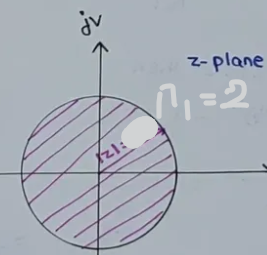
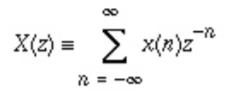
(a) The set of Z for which X(z) is converges (gives finite value)/the set of points in Z-plane for which X(z) is converges is called Region Of Converges.
Differences between Z-transform and Laplace Transform
Z Transform
Laplace Transform
Z transform is mathematical tool used for conversion of time domain into frequency domain (z domain) and is a function of the complex valued variable Z.
an integral transform that converts a function of a real variable (usually , in the time domain) to a function of a complex variable
Used to analyze discrete time signal
continuous time signal
Uses the complex variable Z
uses the complex variable s
The set of points in z-plane for which X(z) converges is called the ROC of X(z)
The set of points in s-plane for which X(s) converges is called the ROC of X(s)
Used for discrete time linear system such as digital filters and sampled data control system
Used for the analysis of CT system such as control system and differential equation
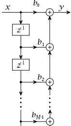
Digital Filters
A digital filter is a system that performs mathematical operations on a sampled discrete time signal to reduce or enhance certain aspects of that signal.
Types : FIR, IIR
Basic element to design Digital Filter
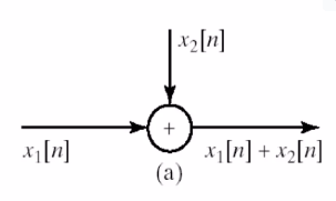
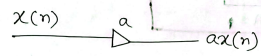
Adder :
Multiplexer
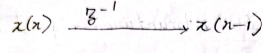
Delay Element
IIR (Infinite Duration Impulse Response) : If the impulse response exists infinitely, it is an IIR Filter.
In this form the frequency response, H(z) is factored into smaller second section, called bi-quads. The frequency response is then represented as a product of these bi-quads section.


.jpg)
.jpg)