Microweb Preparation (Important stuffs only)
| Created by | Borhan |
|---|---|
| Last edited time | |
| Tag | Year 3 Term 2 |
Introduction
Microwave is a line-of-sight wireless communication technology that uses high frequency beams of radio waves to provide high speed wireless connection that can send and receive voice, video and data information.
Wavelength : as long as 1 meter as short as 1 millimeter
Frequency: 300MHz to 300 GHz
The radio spectrum allocated for Microwave are UHF,SHF and EHF (by ITU : International Telecommunication Union)
- Ultra High Frequency (UHF) : 0.3-3 GHz (decimetric waves)
- Super High frequency (SHF) : 3-30 GHz (centricmetric waves)
- Extremely High Frequency (EHF) : 30-300 GHz (milimetric waves, including millimeter waves from 30-100 GHz (wavelength 10mm to 3 mm) )
Microwave frequency bands are designated by specific letters
| Letter | GHz |
|---|---|
| L | 1-2 |
| S | 2-4 |
| C | 4-8 |
| X | 8-12 |
| Ku | 12-18 |
| K | 18-26.5 |
| Ka | 26.5-40 |
| Q | 30-50 |
| U | 40-60 |
| V | 50-75 |
| E | 60-90 |
| W | 75-110 |
| F | 90-140 |
| D | 110-170 |
Applications:
- Point-to-Point Communication:
- Used for telephone communications, especially long distance via microwave replay links.
- Multiplexing allows thousands of two-way calls on a single carrier over a long distance.
- Television Transmission
- TV stations and networks use microwave relay links to send signals over long distances instead of coaxial cables
- Radar System:
- Operates in the microwave region to detect objects’ presence, distance and direction by analyzing reflected signals
- Space Communication
- Essential for satellite communication, deep-space probes and spacecraft as microwaves aren’t absorbed by the ionosphere like lower frequencies.
- Cellular and Internet Networks
- Backbone links and “last mile” connections for cellular operators, ISPs and wireless ISPs
- Corporate networks for building-to-building or campus connectivity
- Other : Radio navigation, sensory systems and radio astronomy.
Microwave Satellite Rx and Tx
Microwave Transmitter
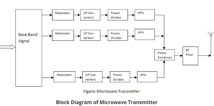
Description
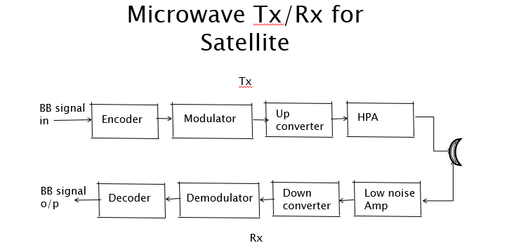
Microwave Transmitter
- Input : Baseband signal (e.g. voice, video, data)
- Encoder : BB into digital format (e.g. PCM for voice)
- Modulator: Modulates the signal onto a carrier, typically an intermediate frequency (IF) of 70 MHz. Common modulation schemes include BPSK, QPSK or QAM.
- Up-Converter: Multiples the IF signal to the uplink frequency, often in the 6 GHz range for the C-band satellites.
- Power divider: Splits the signal for amplification.
- High Power Amplifier (HPA): Boosts the signal using devices like travelling wave tube amplifier (TWTAs) or Klystron Amplifier. These require cooling due to high power.
- Power Combing Amplifier: Combine output from multiple HPA’s for stronger transmission.
- Bandpass Filter and Circulators: Ensure frequency stability and prevent interference.
- Output: The signal is transmitted to the satellite via an antenna,
Important : Highlight the 70 MHz IF, 6 GHz uplink, and HPA types (TWTA/klystron).
Microwave Receiver:
- Input: Receives the downlink signal (4GHz for C-band)
- Low Noise Amplifier (LNA): Amplifies the weak signal with minimal noise addition.
- Down-Converter: Converts the GHz signal to an intermediate frequency (IF) of 70 MHz, typically using a double conversion process.
- Bandpass Filters and Amplifiers: Filter and boost the IF signal to improve strength and quality.
- Demodulator: Extracts the baseband signal from the IF carrier.
- Decoder: Converts the digital signal back to its original form (e.g., voice, video).
- Output: Delivers the baseband signal to the user.
Types of Microweb : Feeder Service vs. Long Haul Microwave Systems
| Feature | Feeder Service Microwave Systems | Long Haul Microwave Systems |
|---|---|---|
| Distance | Short haul: Covers relatively short distances (e.g., between cities within the same state). | Long haul: Covers long distances (e.g., across states or countries). |
| Purpose | Connects nearby locations, often for local or regional communication networks. | Connects distant locations, used for backbone or cross-country communication. |
| Typical Use Case | Local telecom networks, cellular backhaul within a state, or campus connectivity. | Long-distance telecom, TV signal relays, or national/international ISP backbones. |
| Frequency Band | Often uses lower frequency bands (e.g., L, S, C bands) for better penetration over shorter ranges. | May use higher frequency bands (e.g., Ku, Ka) for higher capacity over long distances, depending on conditions. |
| Infrastructure | Requires fewer repeaters due to shorter distances. | Requires more repeaters to maintain signal strength over long distances. |
| Environmental Impact | Less affected by terrain or weather due to shorter paths. | More susceptible to terrain obstacles and weather (e.g., rain fade) over long paths. |
Adatantages
- High Capacity
- Small Antennas
- Shorter Switching center distances
- Low Crosstalk : minimal interference
- Fewer Repeaters
- High Reliability and Low maintenance
- Wide Bandwidth: Microwave band has 30x the bandwidth of lower radio spectrum.
- Efficiency
Disadvantages
- Complex Analysis and Design : Harder to analyze, design circuits, and measure at high frequencies.
- Critical Transient time
- Specialized Components : Costly, specialized parts.
- Line-of-Sight (LOS) limitation: Signals travel in straight line, restricting use to LOS applications
Antenna Fundamentals
- An Antenna is a transducer which converts electrical power into electromagnet waves and vice versa.
- Antenna can be used
- Transmitting : electrical into electromagnetic and radiates
- Receiving: electromagnetic waves into electrical
- Two-way Communication : same antenna can be used for both
- Functionality
- Antennas radiate or receive power through a transmission line.
- It connects to the station’s circuitry via a transmission line
- The radiation mechanism relies on how the transmission line is designed to emit energy.
- Radiation Mechanism: The radiation mechanism explains how an antenna radiates energy using a transmission line.
- Transmission Line: A conductor or a wire designed to carry current over long distances with minimal loss.
- A straight, infinite transmission line with uniform current velocity doesn’t radiate power.
- Waveguide: If the transmission line is bent or terminated, it radiates energy and becomes a waveguide, used specifically for microwave transmission and reception.
- Transmission Line: A conductor or a wire designed to carry current over long distances with minimal loss.
- Mode of Applications : The types of antennas depends on according to the modes of applications:
- Point-to-point communications
- Broadcasting
- Radar
- Satellite communication
- Antennas Parameters: Frequency, wavelength, impedance matching, VSWR (Voltage Standing Wave Ratio) and reflected power, bandwidth, percentage bandwidth, radiation intensity, directivity, gain, aperture efficiency, antenna efficiency
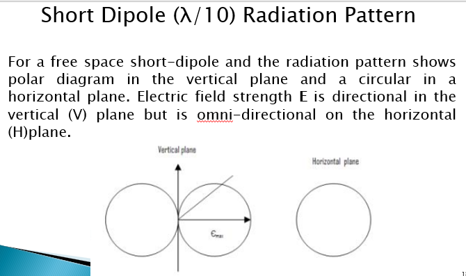
- Radiation Field Pattern: The field pattern shows how an antenna distributes energy in space.
- Filed Pattern: The field distribution can be quantifying in terms of field intensity is referred to as field pattern.
- Electric field pattern/field pattern: the radiated power from the antenna when plotted, is expressed in terms of electric field E.
- Electric field pattern/field pattern: the radiated power from the antenna when plotted, is expressed in terms of electric field E.
- Power Pattern: Quantified in terms of power W
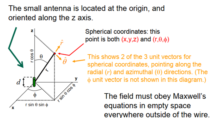
- Coordinate System: Uses spatial angles and radial distance .
- Near Field: The field which is neared to the antenna is called near-field/inductive field. It has sane radiation components.
- Reactive Near field: Very close to the antenna, no significant radiation
- Fresnel Field: Slightly farther, where radiation begins and field distribution depends on distance.
- Far field: Far from the antenna, where radiation dominates, the field pattern is independent of distance. This is where antenna parameters like directivity are measured.
- Also known as radiation field, because radiation effect is high in the area.
- Filed Pattern: The field distribution can be quantifying in terms of field intensity is referred to as field pattern.
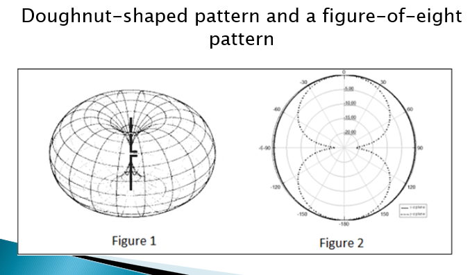
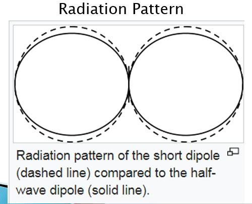
- Radiation Pattern: The radiation pattern is a graphical representation of how an antenna radiates energy in space.
- 3D pattern : Shown the energy in three coordinates (x,y,z)
- 2D pattern: Delivered by slicing the 3D pattern into
- Horizontal pattern: in the horizontal plane
- Vertical pattern
- Types
- Omni-directional/Non directional: Doughnut-shaped in 3D, figure-of-eight in 2D
- Pencil-beam: The beam has a sharp directional pencil shaped pattern
- Fan-beam: fan-shaped pattern
- Shaped beam pattern: The beam which is non-uniform and patternless
- Isotropic radiation: Isotropic radiation is when energy radiates equally in all directions from a point source.
- theoretical concept, practically impossible
- every antenna radiates its energy with some directivity
- Shape : same as omni-directional
- theoretical concept, practically impossible
- Directivity: The ratio of maximum radiation intensity of the subject antenna to the radiation intensity of an isotropic or reference antenna, radiating total power is called the directivity.
- Non-isotropic antenna : the ratio of the radiation intensity in a given direction to the radiation intensity of the isotropic source.
- focused in a particular direction
- Directivity :
- Gain:
- describes how much power is transmitted in the direction of peak radiation to that of an isotropic source
- unit dB
- measures antenna’s performance
-
- : Antenna efficiency
- : Directivity
- : Radiated power
- : Input power
- dB vs dBi : […]
- Lobe formation: Radiation patterns consist of different lobes: main lobe, side lobes, and back lobe.
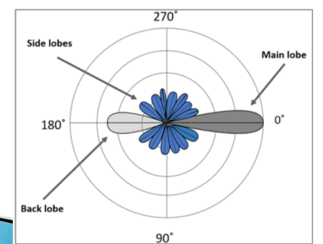
- Main Lobe: The largest portion of radiated field, covering maximum area where most energy is radiated. Its direction indicates the antennas directivity.
- Side Lobes (Minor Lobes): Smaller areas of radiation on the sides, where energy is wasted.
- Back Lobe: A minor lobe opposite the main lobe, also wasting energy.
- Problem: In radar systems, side lobes cause false target detection, making it hard to distinguish real targets.
- Solution: Eliminating side and back lobes by redirecting their energy to the main lobe improves directivity and antenna performance.
- Equivalent Isotropic Radiated Power (EIRP)
- The amount of power that an isotropic antenna radiates to produce the peak power density observed in the direction of maximum antenna gain, is called as Equivalent Isotropic Radiated Power.
- Focusing energy in a specific direction increases EIRP and gain.
- Effective Radiated Power (ERP)
- If the radiated power is calculated by taking half-wave dipole as the reference, rather than an isotropic antenna, then it can be termed as ERP (Effective Radiated Power).
-
- The gain of half wave dipole is
- Beam
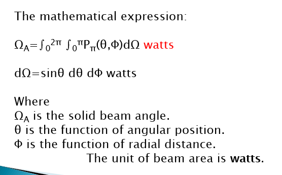
- Beam area is the solid angle through which all the power radiated by the antenna would stream if P (θ, Ø) maintained its maximum value over beam area or beam angle (ΩA) and was zero elsewhere.
- The radiated beam of the antenna comes out from an angle at the antenna, known as solid angle, where the power radiation intensity is maximum. This solid beam angle is termed as the beam area. It is represented by ΩA.
- Beam angle is a set of angles between the half power points of the main lobe.
- Beam Efficiency
- The beam efficiency states the ratio of the beam area of the main beam to the the total are radiated.
-
- Beam Width
- Beam width is the aperture angle from where most of the power is radiated.
- Types
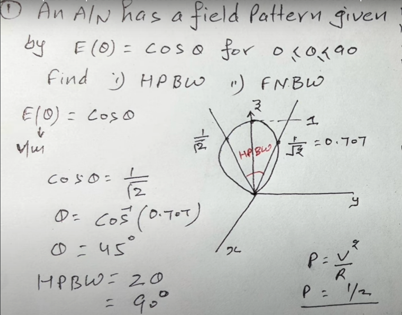
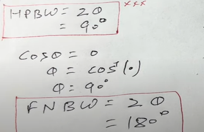
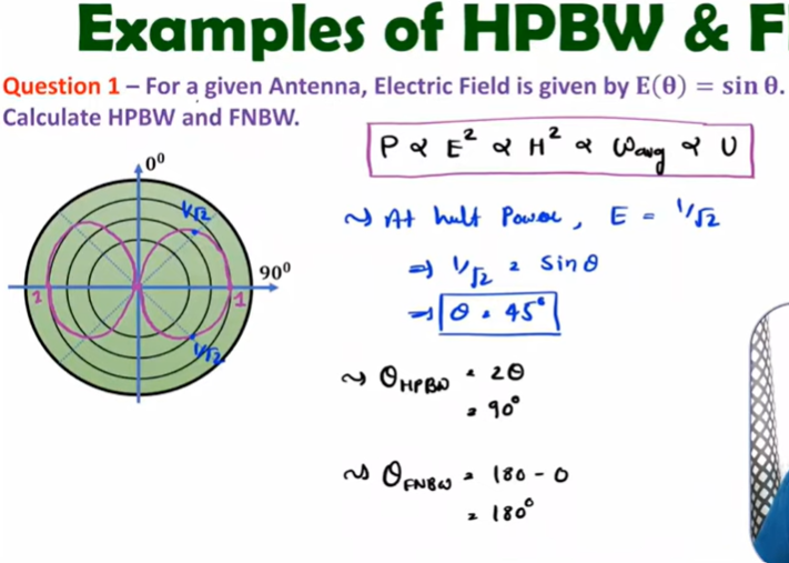
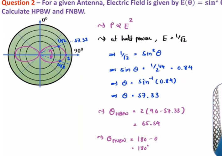
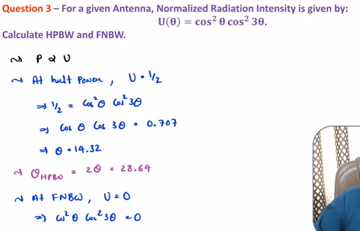
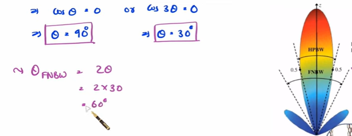
- Half Power Beam Width (HPBW)
- Half power beam width is the angle in which relative power is more than 50% of the peak power, in the effective radiated field of the antenna.
-
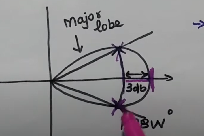
- At this half power point, the field intensity equal times its maximum value.
- First Null Beam Width
- The angular span between the first pattern nulls adjacent to the main lobe, is called as the First Null Beam Width.”
-
- Half Power Beam Width (HPBW)
Hertzian Dipole Antenna
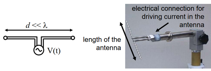
- The Hertzian dipole, developed by Heinrich Hertz around 1886, is a theoretical dipole antenna used to prove Maxwell’s equations experimentally.
- Definition: An infinitesimally small current source in free space. It’s theoretical (not physically possible), but short dipoles approximate it.
-
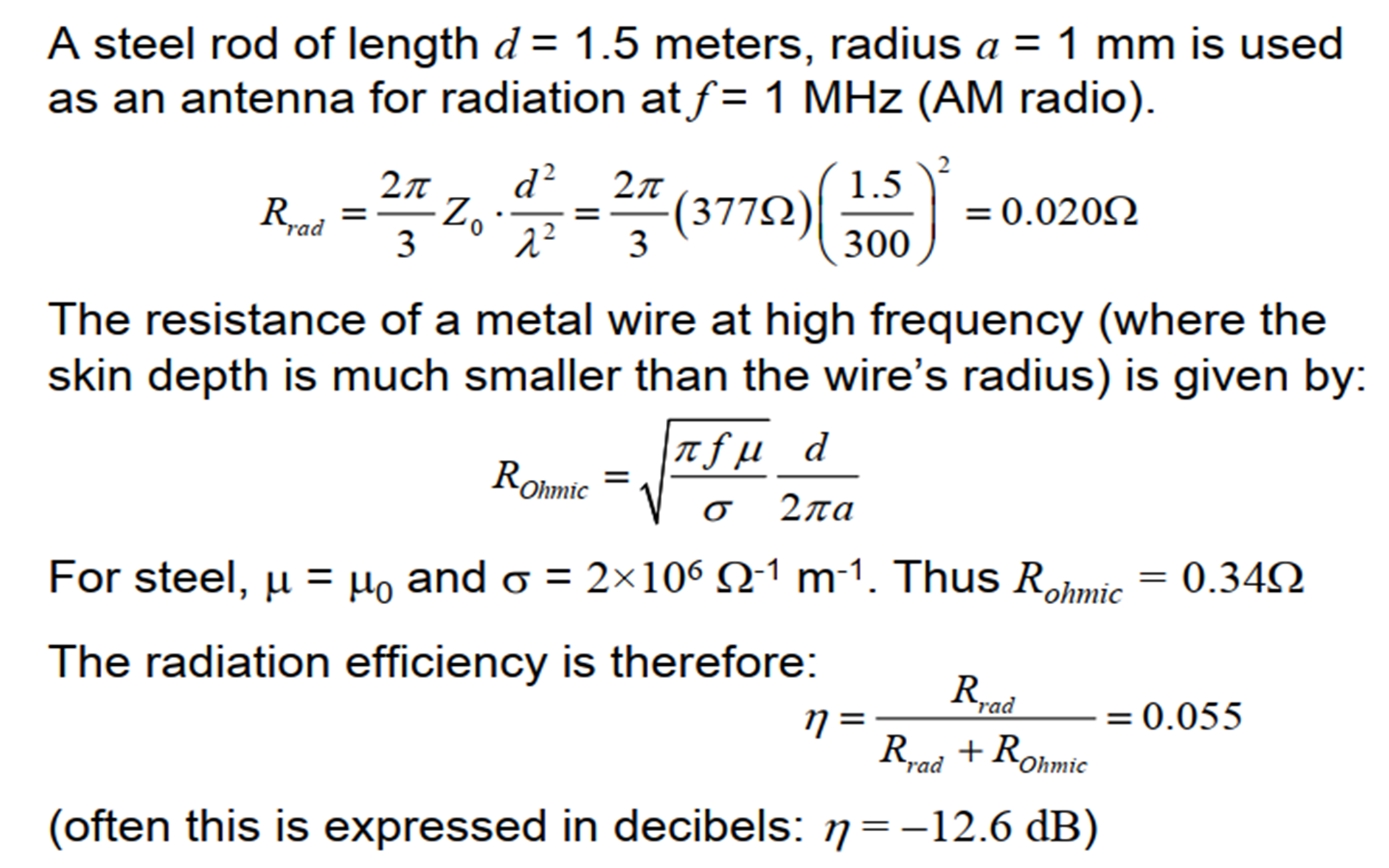
- Radiation Resistance,
-
- The Hertzian dipole is a linear antenna which is much shorter than the free-space wavelength. We can treat this as a wire of infinitesimal length d, carrying a current: I (t) = I0 cos(ωt) → I0 ej ωt
-
- Radiation Resistance,
- , impedance of free space
- If a Hertzian dipole length d= 0.1λ
-
- The radiation efficiency is the percentage of input power that is converted to radiated power.
-
- The theoretical maximum gain of a Hertzian dipole is constant 1.5 which corresponds to 10 log10 1.5= 1.76 dBi. For half wave dipole antenna the maximum theoretical gain is 1.64 which corresponds to 10 log10 1.64 or 2.15 dBi.
- The maximum effective aperture
Dipole Antenna
- A Dipole antenna is defined as a symmetrical antenna in which the two ends are at equal potential relative to midpoint.
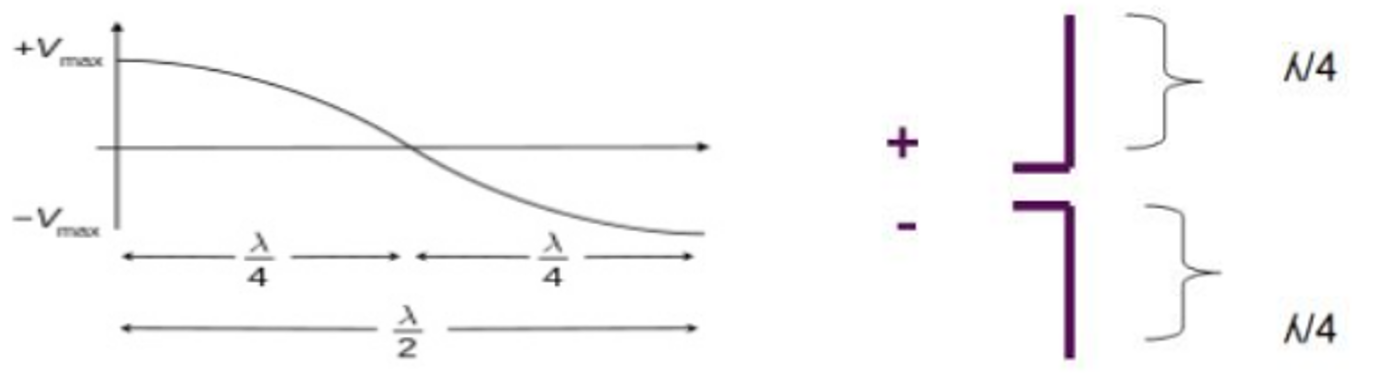
- Half wave dipole antenna: A half wave dipole antenna is the fundamental radio antenna of metal rod thin wire, it has a physical length of half wavelength in free space of the frequency of operation. Example : Yagi-Uda array, log periodic array,
- simplest antenna
- used as an element of more complex directional array system
- Equations for Dipole Antenna
Peak current at the center,
where and z runs from -L/2 to L/2
For far field,
Gain :
Short Dipole (λ/10)
-
- (73 Ω resistance and +43 Ω reactance, )
- Length, [f in Megahertz)
- Feeding a dipole antenna : Ideally, a half-wave dipole should be fed using a balanced transmission line matching its typical 65–70 Ω input impedance.
Many types of coaxial cable (or "coax") have a characteristic impedance of 75 Ω, which would otherwise be a good match for a half-wave dipole. However coax is a single-ended line whereas a center-fed dipole expects a balanced line (such as twin lead).
Much more common use of 300 Ω twin lead in conjunction with a folded dipole. The driving point impedance of a half-wave folded dipole is 4 times that of a simple half-wave dipole, thus closely matching that 300 Ω characteristic impedance. Most FM broadcast band tuners and older analog televisions include balanced 300 Ω antenna input terminals. However twin lead has the drawback that it is electrically disturbed by any other nearby conductor (including earth); when used for transmitting, care must be taken not to place it near other conductors.
- Operating Frequency : 3KHz to 300 GHz
Transmission line
- A transmission line is the channel or medium through which the transmission and distribution of electric power occurs.
- Common lines
- Coaxial Transmission Line
-
-
-
- Microstrip line
- Two wire line
-
-
- Characteristics Impedance,
- For lossless Tx line, R=G=0,
- Coaxial Transmission Line
- Transmission Line Equations
- Characteristics Impedance,
-
- For lossless Tx line, R=G=0,
- Propagation Constant
- , f in hertz
- Input impedance
-
- Normalized Impedance,
-
- Reflection Coefficient
-
- For perfect impedance matching,
-
- Voltage Standing Wave Ratio: VSWR is the ratio of the peak amplitude of a standing wave to the minimum amplitude of a standing wave.
- Standing wave ratio,
-
- Characteristics Impedance,
A 30 meter long lossless transmission line with Z0=50 ohm operating at 2 MHz is terminated with the load ZL=60+j40 ohm. If u=0.6c on the line. Find-
a) The reflection coefficient
b) The standing wave ratio
c) The input impedance
Horn Antenna
- A horn antenna consists of a flaring metal waveguide shaped like a horn to direct radio waves in one direction.
- It is an opened out waveguide capable of radiating radiation into open space.
- Types : Based on its flaring
- Sectoral
- If the flaring is done only one direction
- flare horn wrt/parallel to E plane : sectoral E plan antenna
- flare horn wrt H plane : sectoral H plan antenna
- If the flaring is done only one direction
- Pyramidal
- flaring is done along both E and H fields
- Conical Horn antenna
- flaring the waves of a circular waveguide
- Biconical antenna
- combination of two conical horn antenna
- Sectoral
- Working Principles
- Flaring helps to match the antenna impedance with free space impedance for better radiation.
- The function of the waveguide horn is to produce a uniform phase front with a larger aperture.
- Design
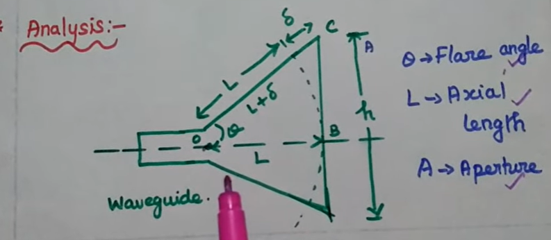
Flare angle, Φ of the horn antenna is an important factor to be considered. If this is too small, then the resulting wave will be spherical instead of plane and the radiated beam will not be directive. Hence, the flare angle should have an optimum value and is closely related to its length.
- If flare angle is large is very large
- non-uniform phase distribution
- High beamwidth
- Reduced directivity
- If flare angle is large is small
- uniform phase distribution
- Beamwidth decreases
- directivity increases
- If flare angle is large is very large
- Application
- works UHF and LHF (300 MHz - 30 GHz)
- Used in microwave application
- Satellite Communication
- active element in a dish antenna
- astronomical studies
- Advantages
- Small minor lobes are formed
- Impedance matching good
- Greater directivity
- Narrower beam width
- Disadvantages
- Designing of flare angle, decides the directivity
- Flare angle and length of the flare shouldn’t be very small
- Equation
- Beam width,
- Gain,
- W : horn width, A = area, k = uniform phase distribution and e.m field amplitude across aperture (0.5-0.6)
Parabolic Antenna
- It is an antenna that uses a parabolic reflector to direct the radio waves in a desired direction.
-
-
- d : diameter of dish openning
-
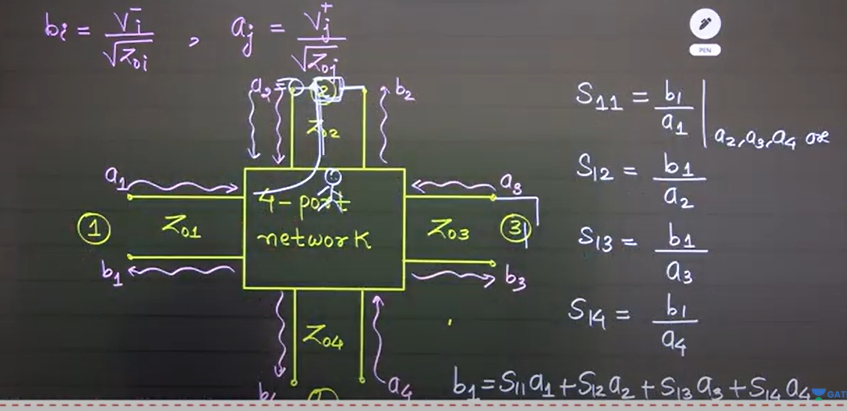
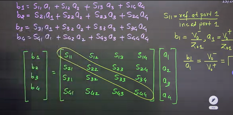
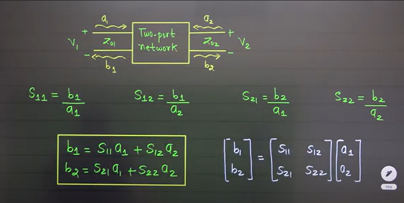
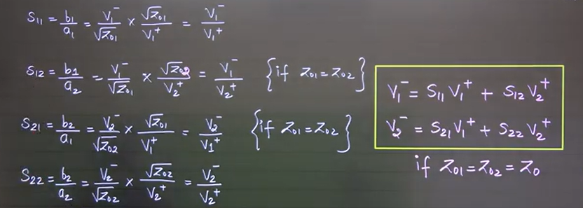
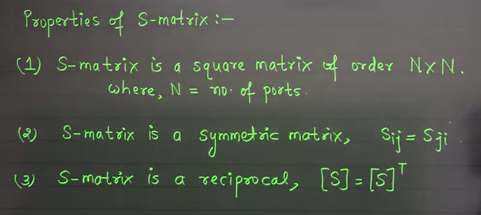
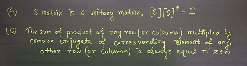
Scattering Parameters
- Scattering parameter is defined as ratio of normalized reflected voltage wave at i-th port to the normalized incident voltage wave at j-th port.
-
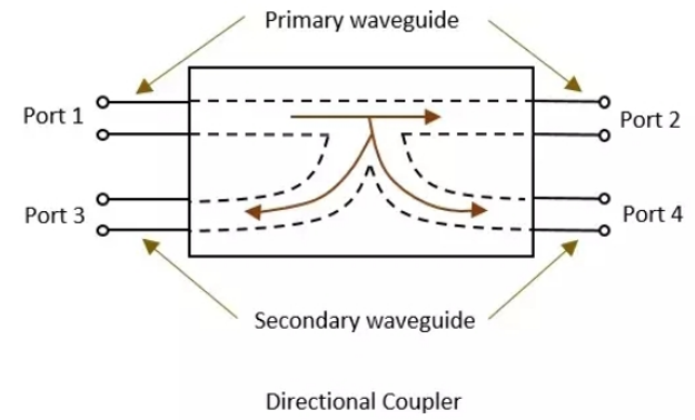
Directional Coupler
- a device that samples a small amount of microwave power for measurement purposes.
- It used to couple the microwave power which may be uni or bi-directional.
- It is a 4 port waveguide junction consisting of a primary main waveguide and a secondary auxiliary waveguide.
- Port 1 : Incident port
- Port 2 : through port
- Port 3 : isolated port
- Port 4 : coupled port
- swap(1,2) ⇒ swap(3,4) possible. [alternative]
- Properties
- All the terminations are matched to the ports.
Travels Coupled not coupled 1 → 2 4 3 2 → 1 3 4 Incident through port 3 2 1 Incident through port 3 1 2 - Port 1 and 3 are decoupled as are port 2 and port 4.
- Ideally, the output of port 3 should be zero.
- but practically a small amount of power called back power is observed at port 3.
- Primary Parameters
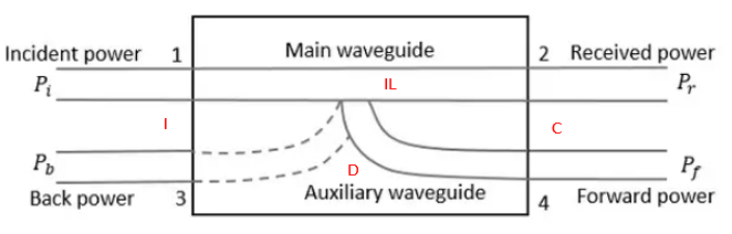
- Port 1 is incident port, there is a insertion loss (IL) in port 1 and 2.
- Isolation (I - ratio of incident power to the back reflected power) between port 1 and port 3.
- Coupling (incident power to the forward power) between port 1 and port 4
- Directivity (forward power to the back power) between port 4 and 3
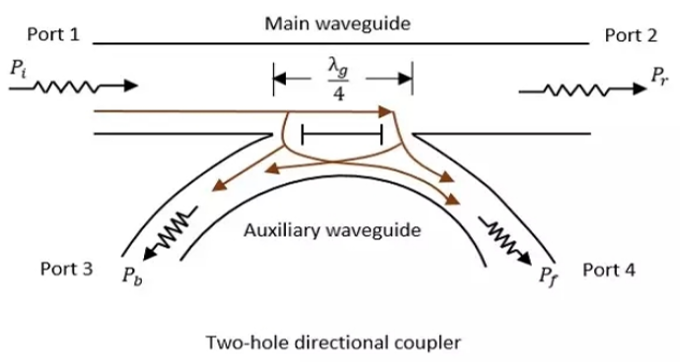
- How built ?
- A basic waveguide coupler uses precisely spaced and sized holes which are a function of wavelength and bandwidth (and the holes may have non-round shapes) to allow power to flow between two physically aligned waveguides. As a result, incident energy on Port 1 mixes with energy incident on Port 3.
| Point | Directional Coupler | Two-Hole Directional Coupler |
|---|---|---|
| What is it? | A 4-port device that splits or couples power. | A special type of directional coupler using 2 holes. |
| How it works? | Couples power from one line to another. | Uses 2 holes spaced λg/4 apart to couple power. |
| Power Flow | Some back power may go to wrong port. | Back power is cancelled due to phase difference. |
| Forward Power | May lose some power. | Holes add power in forward direction (constructive). |
| Back Power | Not fully cancelled. | Cancels out (destructive interference). |
| Directivity | Medium or high. | High directivity. |
| Design | Simple. | More precise (hole distance must be λg/4). |
| Best for? | General RF applications. | When low back power and high directivity are needed. |
Isolator
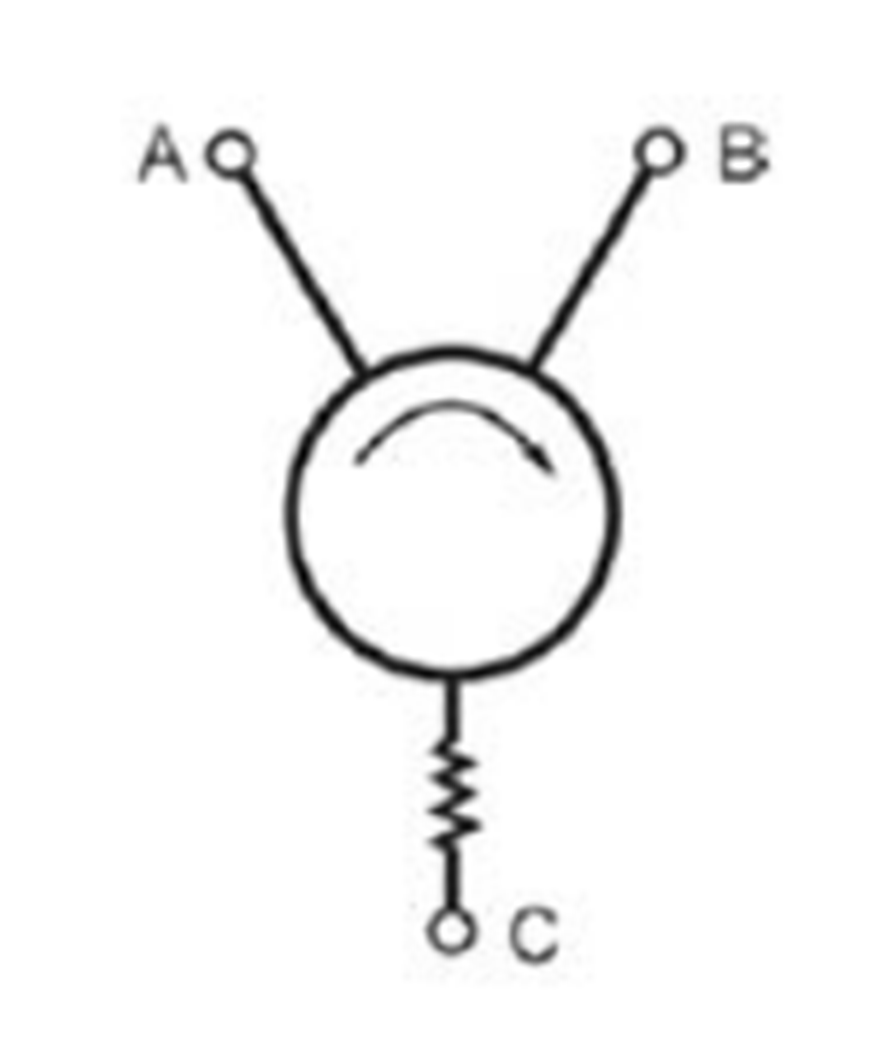
- Isolator is a non-reciprocal device that allows light to pass along a fiber in one direction and offers very high attenuation in the opposite direction.
- To prevent unwanted reflection
- Isolator is circulator but has two ports that transfer a signal
- Working principle
- If signal from port A is well matched with port B, the signal will go into port B with minimal loss.
- If they are not matched the signal will pass to port C, which will dissipate the signal into heat.
- Constructed
- Polarizer : Optical signal passes through polarizer
- Faradays rotator: Rotate the polarization of optical signal by 45 degree
- Analyzer : is oriented at 45 degrees to the input polarizer..
- produces 2 db loss
Circulator
- A non-reciprocal multi-port microwave device (usually 3 or 4 ports).
- Signal entering one port exits from the next port in a circular sequence:
- Example: Port 1 → 2, 2 → 3, 3 → 1.
- Constructed using a symmetrical Y-junction and magnetically biased ferrite.
- Ensures low loss transmission (0.5 dB to 1.5 dB).
- Used to direct signal flow in microwave/RF systems.
Phase Shifter
- A reciprocal 2-port device that changes the phase angle of transmitted signals.
- Keeps amplitude same while changing phase.
- Types: analog or digital; may use delay lines, varactors, etc.
- Key features:
- Low insertion loss across all phase states.
- Equal amplitude for all phase shifts.
- Flat phase vs frequency (true time delay possible).
- Applications:
- Phased array antennas, beam steering.
- Any system needing precise phase control without affecting signal power.
| Feature | Isolator | Circulator | Phase Shifter |
| Definition | Allows signal in one direction only, blocks reverse | Routes signal from one port to the next port in a circle | Shifts the phase of signal without changing its magnitude |
| Type of Device | Non-reciprocal 2-port device | Non-reciprocal 3 or 4-port device | Reciprocal 2-port device |
| Main Purpose | Protects devices from reflected signals | Routes signals between ports in a defined sequence | Changes the phase angle of a signal |
| Working Principle | Uses Faraday rotation | Uses Y-junction with magnetized ferrite | Uses delay lines or varactors |
| Signal Flow | Port A → Port B only (blocks B → A) | Port 1 → 2, 2 → 3, 3 → 1 (or circular path) | Same signal goes through, but with phase shifted |
| Ports | 2 (3rd port used for termination) | Typically 3 or 4 | 2 |
| Insertion Loss | ~2 dB | ~0.5 – 1.5 dB | Ideally low in all phase states |
| Key Property | Blocks unwanted reflections | Allows directional signal routing | Provides variable or fixed phase shift |
| Reciprocal? | No | No | Yes |
| Common Use | Between source and load to block reflected power | In radar or duplex communication systems | In phased arrays, beam steering, RF control systems |
Radar
- Radio Detection and Ranging System.
- Detects location and distance of objects using electromagnetic energy.
- Operating range: UHF and microwave frequencies (400 MHz to 40 GHz).
- Functionality
- Purpose : Detect, track, locate and identify object
- Capabilities: Determines distance. velocity, shape, size
- Comparison with other sensors: Superior for detecting faraway targets
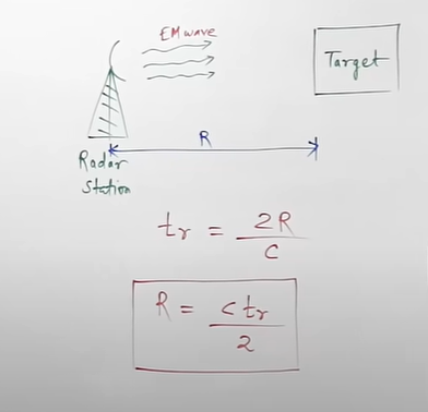
- RADAR Principle
- Similarity to sound-wave reflection (echo principle).
- Process: Transmits electromagnetic energy, receives echoes, and calculates distance based on signal return time.
- Signal speed: Radio signals travel at 300,000 km/s.
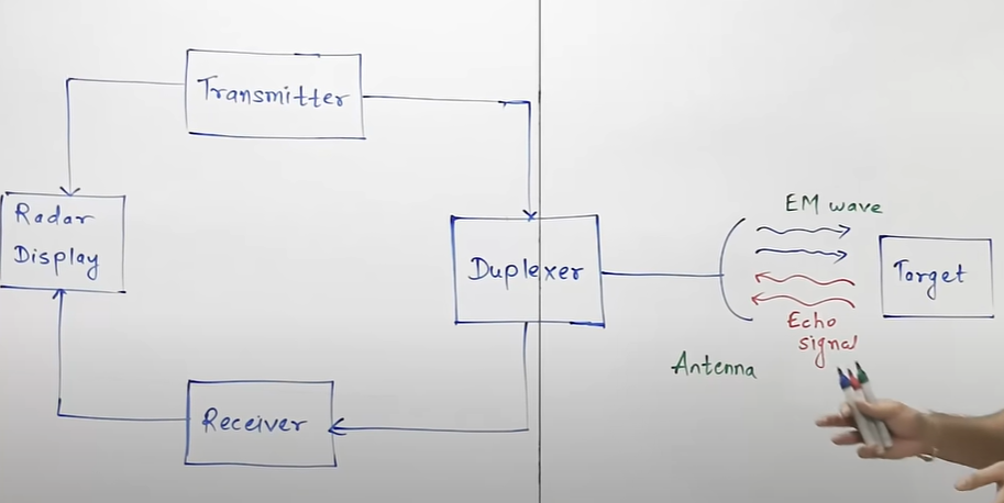
- Design Elements of RADAR
- Transmitter: Generates high-power RF pulses (e.g., Klystron, Travelling Wave Tube, Magnetron)
- Waveguides: Transmission lines for radar signals.
- Antenna: Parabolic reflector, planar arrays, or phased arrays; transmits and receives signals.
- Duplexer: Allows the antenna to switch between transmitting and receiving modes.
- Receiver: Processes signals (e.g., super heterodyne receiver) to detect targets.
- Threshold Decision: Compares receiver output to a threshold to distinguish targets from noise.
- Indicator: Displays a continuous, graphical representation of target positions.
- Radar Range Equation
[Radar cross-section (σ) of the target.]
⇒
- Pulsed Radar
- Operates with pulse signal
- Types
- Basic Pulse Radar : Detects stationary targets using a single antenna and duplexer
- Moving Target Indication (MIT Radar) : Detects non-stationary targets using Doppler effect
- Low pulse repetition frequency to avoid range ambiguities.
- Signal processing: Echo signals mixed with STALO (Stable Local Oscillator) and COHO (Coherent Oscillator) to produce IF signals, amplified, and phase-detected.
- Tracking Radar
- Tracks one or more targets by monitoring range, angle, or Doppler frequency shift.
- Functions before tracking:
- Target detection.
- Determining range, elevation, and azimuth angles.
- Measuring Doppler frequency shift.
- Primary tracking method: Angular tracking.
- Sequential Lobing:
- Alternates antenna beams between two patterns to detect angular error.
- Provides magnitude and direction of angular error with high accuracy.
- Conical Scanning:
- Continuously rotates antenna beam to track targets.
- Uses conical scan modulation to determine target position.
- Squint Angle: Angle between beam axis and rotation axis; modulates echo signal amplitude.
- Sequential Lobing:
- Applications of RADAR
- Military Applications:
- Air defense: Target detection, recognition, and weapon control.
- Missile guidance.
- Mapping enemy locations.
- Air Traffic Control:
- Monitors aircraft positions near airports.
- Guides aircraft landings in bad weather (Precision Approach RADAR).
- Scans airport surfaces for vehicle positions.
- Remote Sensing:
- Observes weather, planetary positions, and sea ice for navigation.
- Ground Traffic Control:
- Measures vehicle speed and monitors traffic flow.
- Provides warnings for vehicles.
- Space Applications:
- Guides spacecraft for safe landings (e.g., on the moon).
- Observes planetary systems.
- Tracks satellites.
- Military Applications:
Satellite Communication:
- How a satellite works?
- A satellite is a body that moves around another body in a particular path. A communication satellite is nothing but a microwave repeater station in space.
- A repeater is a circuit, which increases the strength of the received signal and then transmit it. But, this repeater works as a transponder, means it changes the band of the transmitted signal from the received one.
- The frequency with which the signal is sent into the space called as Uplink frequency. Similarly, the frequency with which, the signal is send by the transponder is called downlink frequency.
- Orbital elements: Orbital elements are the parameters which are helpful for describing the orbital motion of satellites.
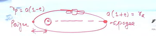
- Semi major axis : The length of semi-major axis (a) defines the size of satellite orbit. It is half of the major axis. This runs from the center through a focus to the edge of the ellipse. So, it is the radius of an orbit at the orbit’s two most distant point.
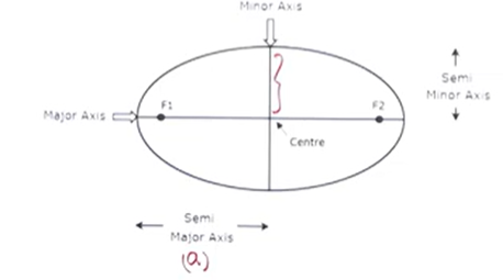
- Eccentricity : The value of eccentricity (e) fixes the shame of satellites orbit. This parameter indicates the deviation of the orbit’s shape from a perfect circle. The value of eccentricity of a circular orbit is zero.
- Mean anomaly
The point which is closet from the earth is known as Perigee. Mean of anomaly gives the average value of the angular position of the satellite with reference to perigee.
- Argument of perigee
- Argument of perigee is the angle between ascending node and perigee.
- Inclination
- The angle between orbital plane and earths equatorial plane is known as inclination
- Right ascension of ascending node
- Semi major axis : The length of semi-major axis (a) defines the size of satellite orbit. It is half of the major axis. This runs from the center through a focus to the edge of the ellipse. So, it is the radius of an orbit at the orbit’s two most distant point.
- Orbital Equations
- Forces acting on Satellite
- Centripetal force : pulling from the earth due to earth’s gravitational force.
-
- Centrifugal force: pulling from the sun and the moon due to their gravitational forces. tends the satellite away from earth.
-
- v : orbital velocity of satellite
- Orbital Velocity of satellite is the velocity at which it revolves around earth.
- Orbital Velocity of satellite is the velocity at which it revolves around earth.
- Centripetal force : pulling from the earth due to earth’s gravitational force.
- Forces acting on Satellite
Kepler’s Laws
…
Satellite Link Budget
- Power transmitted by the satellite,
- Power density of distance ‘R’,
- Power received at the receives,
-
- antenna efficiency
-
-
In Decibel,
- Cearrier-to-noise ratio
-