Computer Architecture and Organization : CT 2
| Created by | Borhan |
|---|---|
| Last edited time | |
| Tag |
Syllabus: Chapter 2, 4 and chapter 7 micro operation পর্যন্ত।
Resources:
- Chapter 4, Cache Memory: https://www.youtube.com/watch?v=OfqzoQ9Kw9k&list=PL3R9-um41JswfYyN5cxfhAmld_JTaYYwE&index=1
- Memory Access Method : https://www.youtube.com/watch?v=4FB7qdXC_z8
- Memory Hierarchy: https://www.youtube.com/watch?v=zwovvWfkuSg
- Register Transfer and Microoperation (1-4) : https://www.youtube.com/watch?v=mNNywW00eEc&list=PLoAiV2nk2_iEK1YJf_Dx2t-UuBpnK_Byh
- Memory Hierarchy - Cache Memory : https://web.njit.edu/~sohna/cs650/lec7.pdf
Ch.2 : Performance Measuring
- Clock Cycle Time
- Time between two consecutive rising or trailing edges of a periodic clock signal
- it allows counting unit computation
- CPI (Clock Cycle per Instruction)
- an alternative performance measure, because it is easier
If for each instruction category is known, then overall can be computer as
- MIPS (Million Instruction-per-second) : The rate of instruction execution per unit time
- a performance measure for machines
- It measures the rate of average instructions
- It does not track execution time
- MFLOP (Million floating-point instructions per second): The rate of floating point instruction execution per unit time
- measure of machine’s performance
- is defined the subset of floating-point instructions
- Summarize performance regarding larger sets of programs
- Arithmetic Mean
- Geometric mean
- Arithmetic Mean
- Amdahl’s Law
- Is a formula used to find maximum improvement possible by improving particular part of a system
- In parallel computing it is mainly used to predict the theoretical maximum speed up for program processing using multiple processor
- related to speed up of parallel computer
- when a program run on parallel computer then the computation may be
- serial
- parallel
- both
- there will be certain part of program
-
-
- Amdahl’s formula, speed up,
- Speedup is the ratio of the it takes to execute a program in serial(one processor) to the time it takes to execute in parallel (many processors.)
- Proof:
It based on a fixed problem size.
Amdahl’s law tells that a giver problem size, the speedup doesn’t increase linearly as the number of processor increases. Speed up tends to become saturated.
Speed up formula, …
Execution time for single processor =
Execution time for parallel processor
From, equation ,
or,
Ch. 4 : Cache Memory
- small size fast memory
- placed between main memory & CPU
- high speed volatile memory
- contains most frequency accessed instruction data
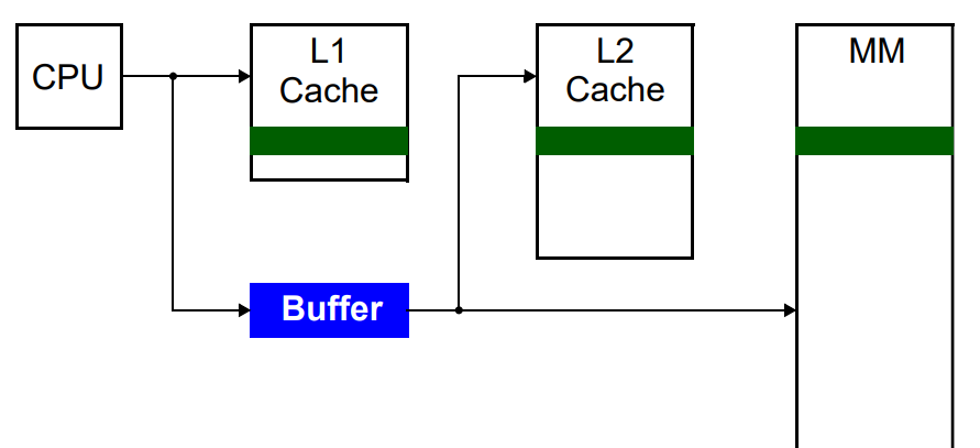
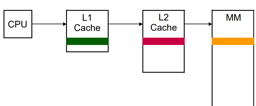
- Located inside the CPU chip (internal cache L1 and L2) or motherboard (external cache, L3)
CPU → L1 → L2 → L3 → Main Memory
Memory Access method
- Sequential
- whenever any access request arrives, the memory is searched from the beginning till the required data found
- simple but slow
- time is variable
- Random access
- Data present at any memory location can be accessed directly
- Time is constant
- Fastest
- Example : RAM
- Direct Access
- It is a semi-random mode of operation in which data is stored in locks/tracks which be accessed randomly. Then find the memory location from the block/track sequentially.
- Time is variable
| Memory Access Method | Description | Advantages | Disadvantages |
|---|---|---|---|
| Direct Access | Directly accesses memory location using an index or address | Fast retrieval of data | Limited flexibility, requires contiguous memory allocation |
| Sequential Access | Accesses memory sequentially, reading data in order | Simple implementation, suitable for linear data structures | Slow for random access, inefficient for large data sets |
| Random Access | Accesses memory locations randomly without sequence | Fast access to any element, suitable for non-linear data structures | Requires additional data structures for indexing, overhead for maintaining index |
| Associative Access | Accesses memory based on content rather than address | Flexible, efficient for search operations | Complex implementation, higher hardware requirements |
Memory Hierarchy
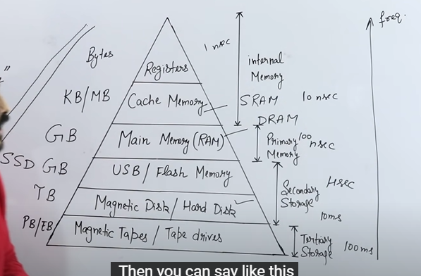
Access time, size both are increasing from top to bottom
Cost and frequency both are increasing from bottom to top
Working of Cache
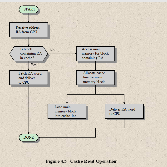
- The CPU initially looks in the cache memory for the data it needs
- If the data there, it will retrieve it and process it
- If the data is not there, then the CPU access the system memory and then puts a copy of the new data in Cache memory
- Next time, if the CPU needs to access the same data again it will retrieve the data from cache instead of main memory
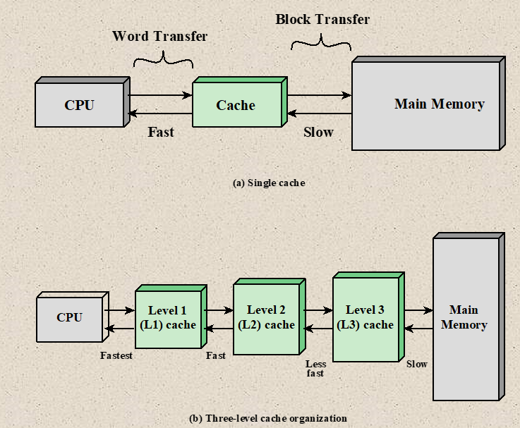
Data transfer between cache and main memory → in blocks
Data transfer between CPU and cache memory → in words
Cache Hit: If the required data is found in cache
Cache Miss: If the required data is not found in cache
Cache access time (Cache Hit time): Time required to access word from the cache
Miss Penalty (Cache Miss Time Penalty) : The time required to fetch the required block from main memory
Write through procedure: Changing something in Cache memory, immediately changes in main memory too. Information is written to both the block in the cache and to the block in the MM.
Write back procedure: Changing something in Cache memory, doesn’t immediately change in main memory but when it removes from cache. Information is written only to the block in the cache. The modified cache block is written to MM only when it is replaced. This requires an additional information (either hardware or software), called dirty bits.
Cache Performance
- it is measured by in terms of Hit Ratios
-
-
-
Example:
The access time of a cache memory is and that of main memory . It is estimated that percent of the memory request are for read and remaining percent for write. The hit ratios for read access is only is . A write through procedure is used.
(a) What is the average access time of the system considering only memory read cycle and write cycle separately ?
Ans:
Average read access time
Total write access time
(b) What is the average access time for both read and write cycle?
Ans:
Average access time for both =
(c) What is hit ratio taking into consideration the write cycle?
Ans:
Hit Ratio taking
[Hit Ratio for only write is assumed as 0]
Cache Organization
Locality of Reference
Also known as Principle of Locality.
- Locality of reference is the tendency of processor to access the set of memory locations repetitively over a short period of time.
Two types of locality of reference:
- Temporal Locality
- if a program access one memory address, there is a good chance that it will access the same address again
- It refers to reuse of specific data/resource within a short period of time
- Example: Loop
- Spatial Locality (Data locality)
- if a program access one memory address, there is a good chance that it will access other nearby addresses
- It refers to use of data elements within relatively class storage location
- Example: Nearly “every program” exhibits spatial locality
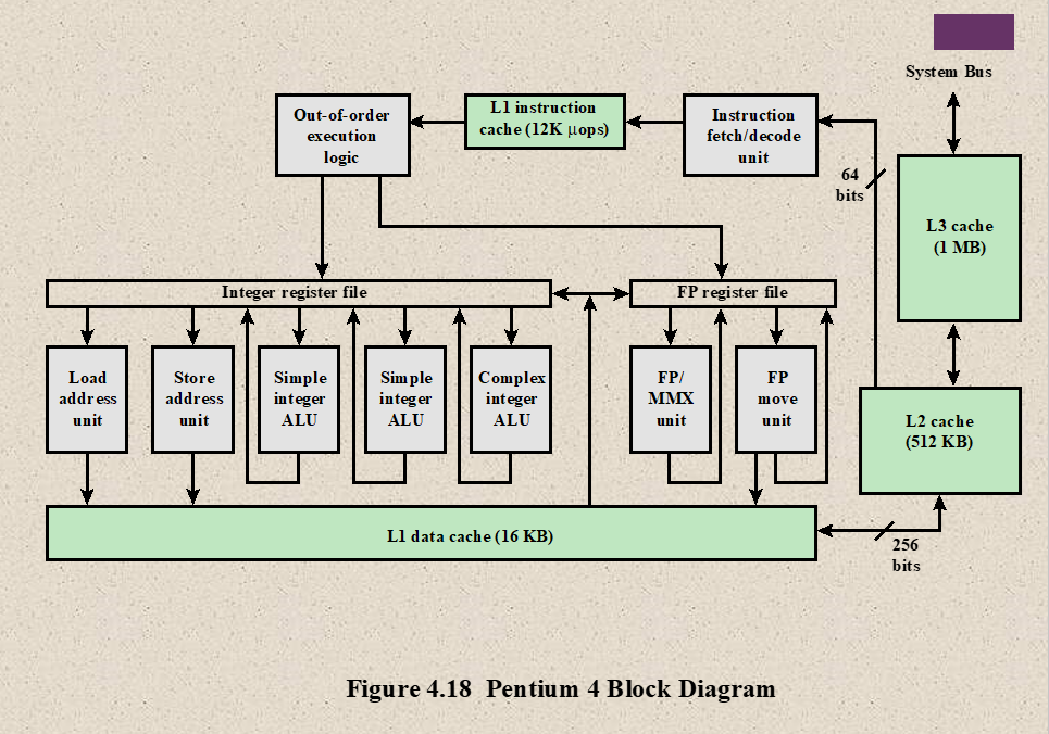
Level of Cache Memory
Level 1 (L1) Cache:
- fastest cache because it is within the processor
- size 8KB to 64KB , that’s why instruction and data are stored together
- uses the high-speed SRAM(Static RAM)
- It is also called Internal cache or Primary cache.
Level 2(L2) Cache:
- Larger but slower than L1 Cache
- Stores recently accessed information
- Also known as Secondary Cache, it is designed to reduce the time needed to access data in case where data has already been accessed previously
- It comes between L1 and RAM.
- Size ranges from 64KB to 4MB
Level 3 (L3) Cache:
- It is built in the motherboard
- It is used to feed/support L2 cache
- It is faster than system memory
- size ≥ 3 MB
Cache Mapping
- Cache Mapping is a technique by which content of main memory is brought into the cache memory
- Main memory divides in blocks and cache memory divides in lines
Connections:
CPU → Cache → Main Memory → Secondary Memory (Hard Disk)
- Paging is a technique by which content of secondary memory is brough into main memory
3 Types:
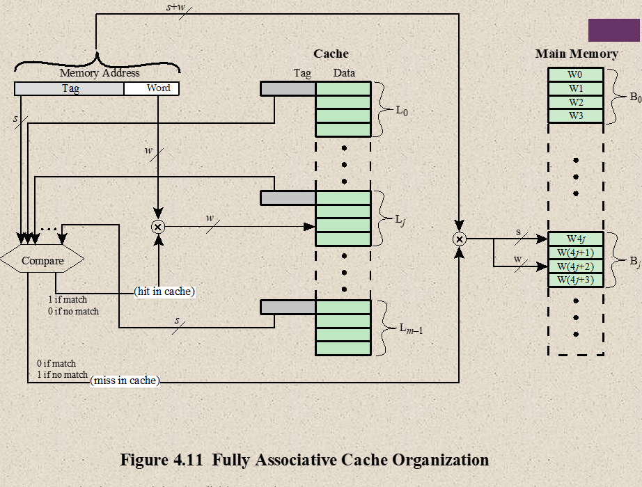
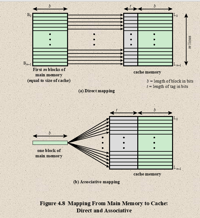
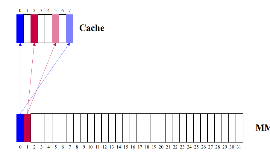
- Associative Mapping
- Fastest, most flexible, uses Associative Memory
- In associative mapping cache are made up of Associative memory. Associative memory is used to store both the address and content/data of the memory word.
- It permits any location in cache to store any word from main memory. It enables any word from main memory at any place in the cache memory.
- If associative cache memory doesn’t have any space/empty location, then it uses Replacement policy/algorithm to which one will be replaced
- FIFO
- LRU (Least Recently Used)
- LFU (Least Frequently Used)
- Random
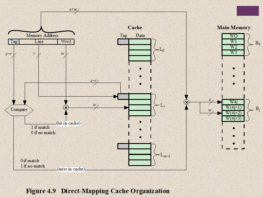
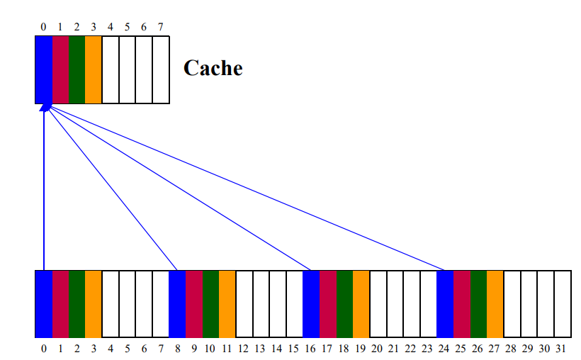
- Direct Mapping
- Associative memory are expensive compared to RAM. (because of added matching logic is attached)
- For RAM, Direct Mapping is used
- Simplest technique
- it maps each block of main memory into only one possible cache line
- CPU address as address space is divided into 2 parts
- Tag : Most Significant Bits
- Index : Least Significant Bits
- Direct Mapping drawbacks
- Two words with the same index in their address with different tag values cannot reside in cache memory at the same time
Questions:
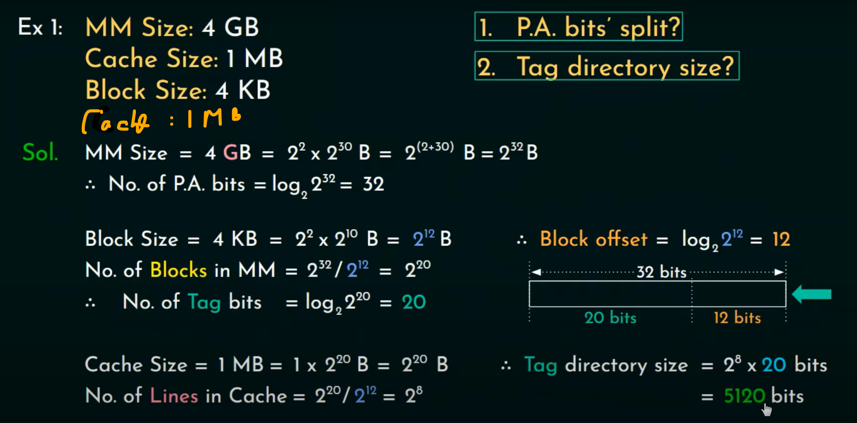
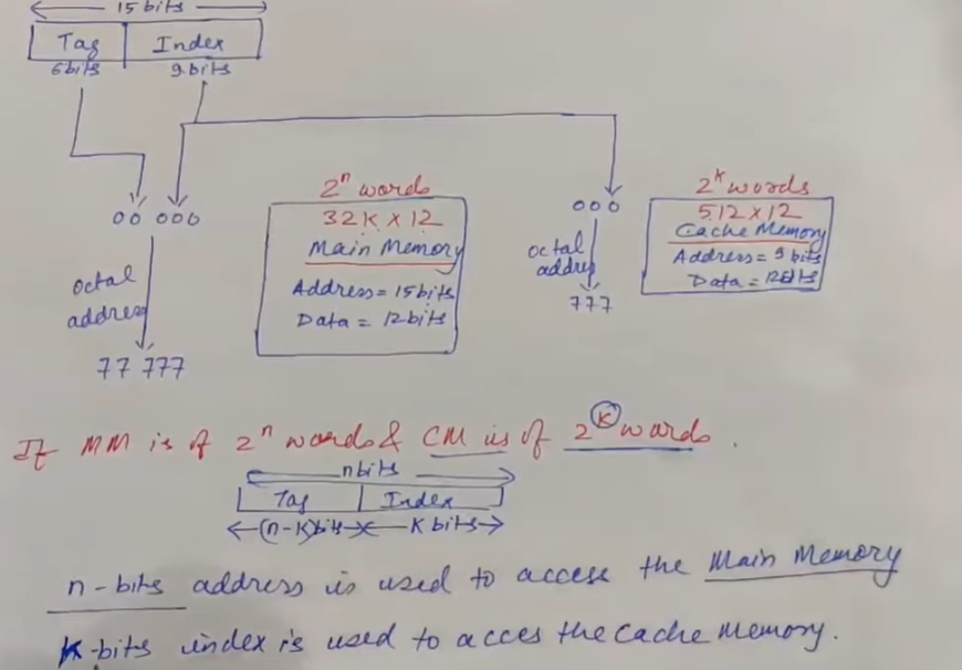
- A digital computer has memory unit of and a cache memory of words. The cache uses direct mapping with a block size of four words.
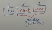
a) How many its are there in the tag, index, block (line) and word (block offset) filed of address formula ?
Ans:
Main memory is represented as :
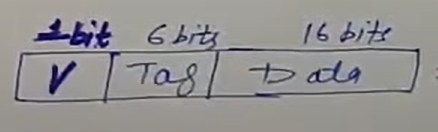
b) How many bits are there in each word of cache and how are they divided into functions ? Include a valid bit.
[Valid bit is one bit only (0 or 1)]
Ans: 23
c) How many blocks can accommodate ?
Ans:
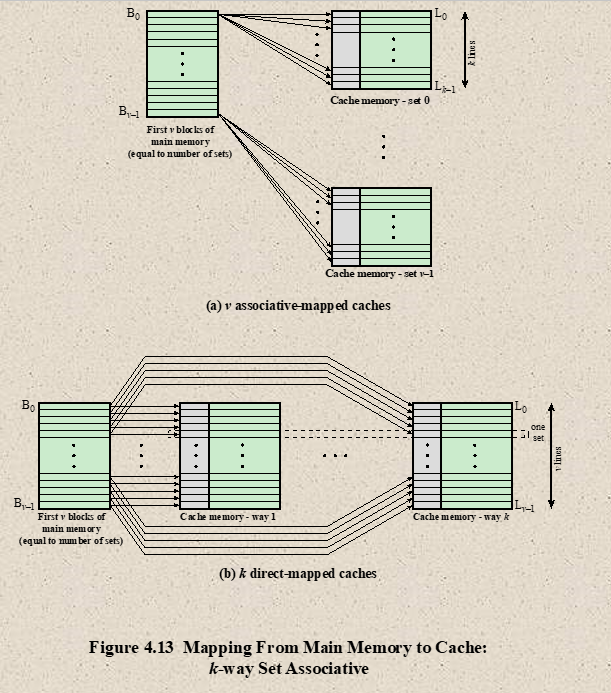
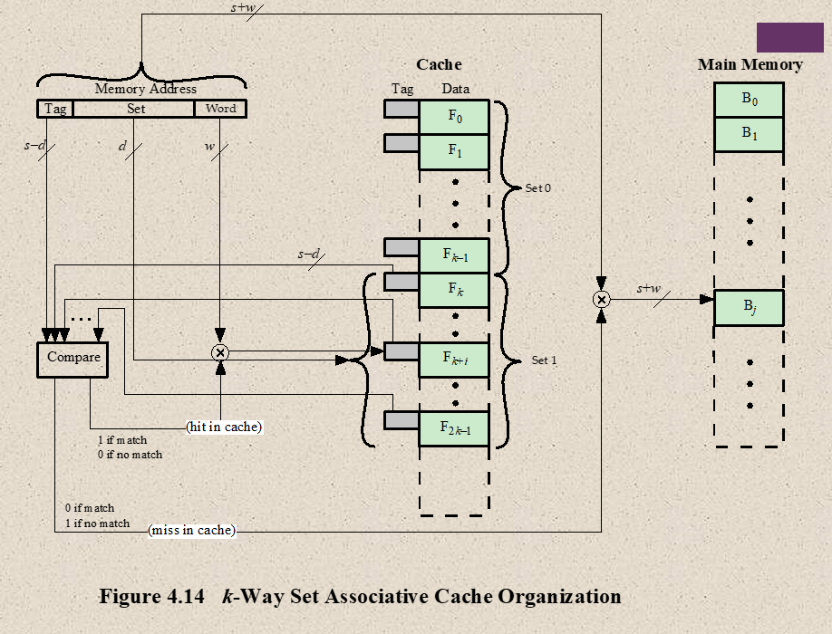
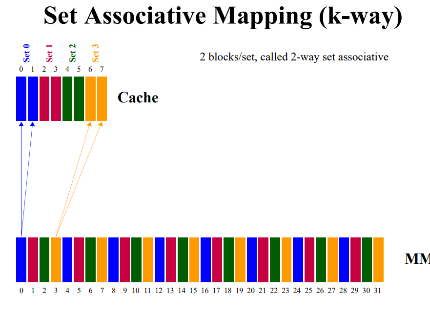
- Set-Associative Mapping
- combines of Direct and Associative Mapping
- Each word of cache can store two or more words of memory under the same index address, creating a set
- Each data word is stand together with it’s tag.
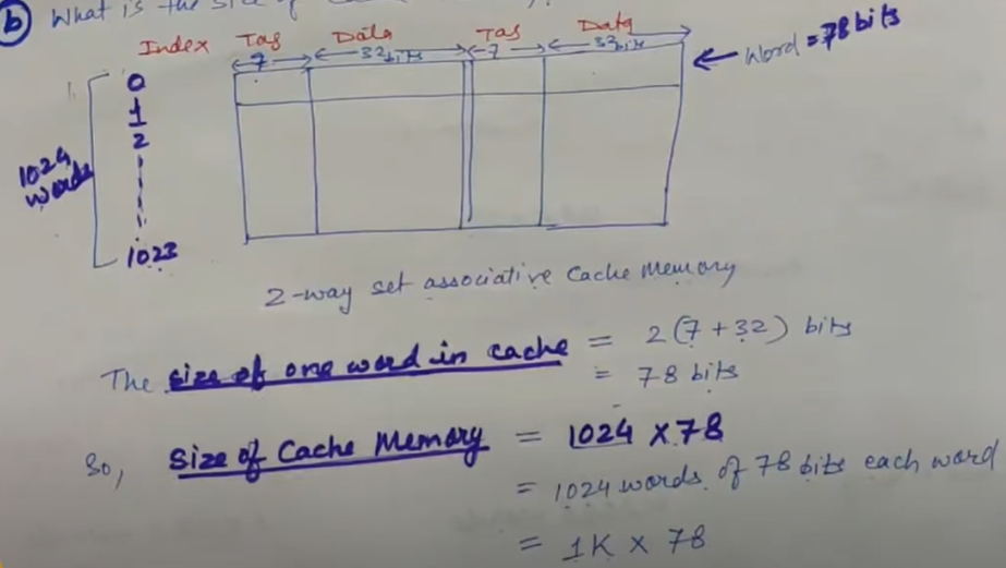
Question
A two way set-associative cache memory uses block of four words. The cache memory can accommodate a total of words from main memory. The main memory size is
a) Formulate all permitted information to construct the cache memory. (Tag, index, data, blocks (set no.), words)
Ans:
b) What is the total size of Cache Memory ?
Virtual Memory
- It appears to be present but actually not
- It provides an illusion of a large memory
- Virtual Memory is a technique allows users to use more memory for a program than the real memory of a computer
- Virtual Memory is the concept that gives an user that they will have main memory equal to the capacity of secondary storage.
- It is a temporary memory is used along with the RAM or main memory.
- VM is a Memory Management Capability of an operating system that uses hardware and software to allow a computer compensate for physical memory shortage by temporary memory data from RAM to disk Storage.
- The basic idea of VM is to keep only those parts of the program currently in use in the memory and the rest on disk drive.
How the VM is implemented
- To implement VM, a portion of Hard disk (HDD) is reserved by the system. This portion can be either a file or a separate partition.
In Windows it is a file called pasefile.sys
In Linux, it is a separate partition.
- When the system needs more memory or RAM, then it transfer some of its data from RAM to hard disk. (Swapping between the main memory and hard disk)
- The size of virtual memory is limited by
- the addressing scheme of computer system
- the amount of the secondary memory available
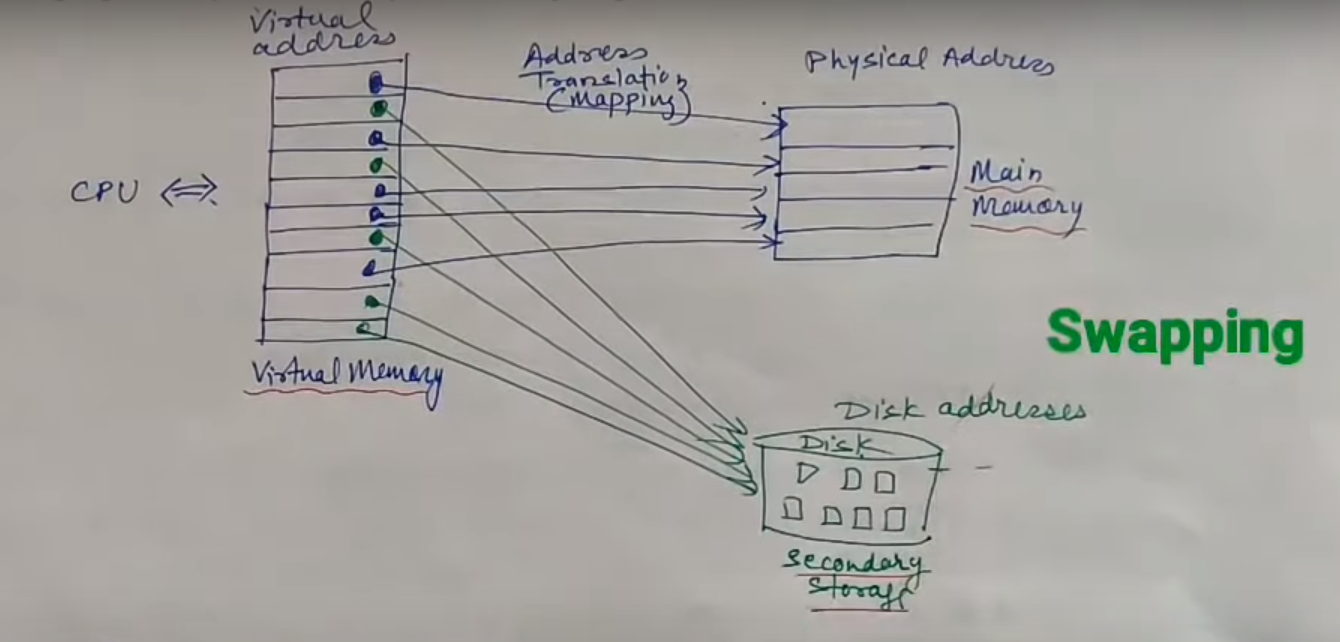
In virtual memory, there are the address of main memory and secondary memory. When a secondary memory address gets, it transfer it’s to HDD to Main memory (which is know as Swap-in). Besides, it transfer those paused main memory task to HDD which is called Swap-out.
Virtual Address/Logical address: Virtual address is the address used by the programmers. The set of such addresses is called address space or virtual memory.
Physical Address: An address of main memory is called Physical Address. The set of such locations in main memory is called the Memory Space or Physical Memory. Physical address is stored in Memory Adder Register (MAR).
- Virtual memory system provides a mechanism for translating program-generated address into main memory locations dynamically. The address translation or wrapping is handled automatically by the hardware by means of a “Mapping Table”.
Cache replacement policies
Cache replacement policies (also known as cache replacement algorithms or cache algorithms) are optimizing instructions or algorithms which a computer program or hardware-maintained structure can utilize to manage a cache of information
- FIFO : Like a FIFO queue
- LIFO : stack
- Optimal Replacement: won’t be referred for the longest period of time in future, theoretical, cannot be implemented
- MRU : most recently used block, works with cyclic pattern
- LRU: temporal locality, least recently used block
- LFU : least frequently used, frequently is recorded, in case of tie fifo used
Placement Policy:
- Direct Mapping
- each block of MM has only one place it can appear in the cache
- Cache address = (MM block address)%(block in cache)
- Associative Mapping
- A block of MM can be anywhere in the cache
- Set Associative Mapping
- A block of MM can be placed anywhere within the set
- Cache address = (MM block address)%(block in cache)
Identification Policy
- Direct Mapping
- 1 Comparison
- Cache address = (MM block address)%(block in cache)
- Associative Comparison
- MM block can appear anywhere in the cache
- need to compare all the tags
- Set Associative Mapping
- K comparison
- Cache address = (MM block address)%(block in cache), have to check a particular set that has K blocks
Ch.7 : Register Transfer and Microoperations
Microoperations
The operations on the data in registers are called microoperations.
A microoperation is an elementary operation performed on information stored in one or more register. Result of operation way replace the previous binary information of a register or may be transferred to another register.
Example : a++, (replaced the previous register) a = b+c; (transferred to another register)
Register Transfer Language
The symbolic notation used to describe the microoperation transfers among register is called Register Transfer Language.

Information transfer from one register to another is designated in symbolic form by meant of replaced operations,
, Information transferring from to
Under a predefined condition/Control function
If then
Symbol :
- Letters, with numerical or not → Denotes a register → MAR, R2
- Parentheses → Denotes a part of register → R2(0-7), R(L)
- Arrow → Denotes the transfer of info →
- Comma → Separates two microoperations, two or more operations are to occur simultaneously
- Colon: denotes termination of control function →
Microoperations
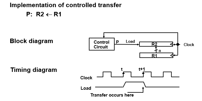
- Register Transfer
Copying the contents of one register to another is a register transfer.
- not destructive
- takes one clock pulse
It implies that
- the data lines from source register to destination register
- parallel load in the destination register
- control lines to perform action
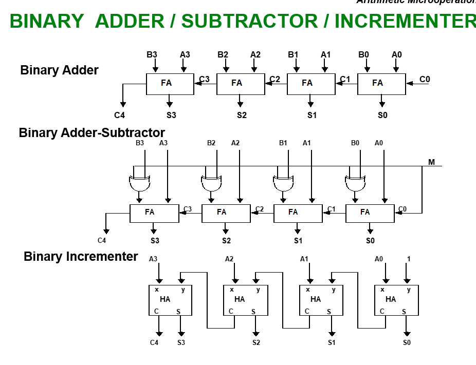
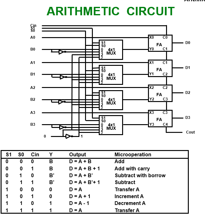
- Arithmetic Microoperations
- Addition →
- Subtraction →
- 1’s compliment →
- 2’s compliment →
- Subtraction :
- Increment →
- Decrement →
Multiplication and division are not basic micro operation but valid operation.
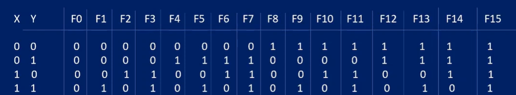
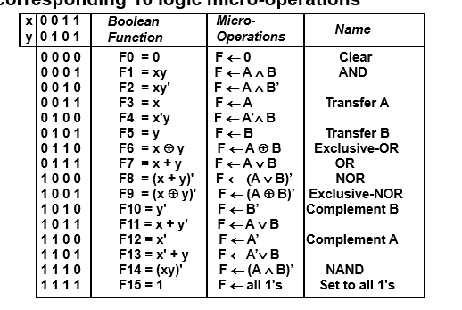
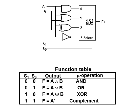
- Logic Operation
A group of bits called strings is stored in the register, the logic microoperation consider each bit of register as compared to the arithmetic microoperation where we take whole content of register to perform arithmetic operation.
- And →
- OR →
- Shift Operation
Shift microoperation transfer binary bits between the register serially. This shift operation is also used to perform binary multiplication and division.
Left shift →
Right shift →
For one bit shifting
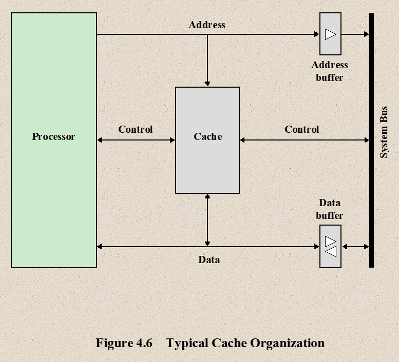
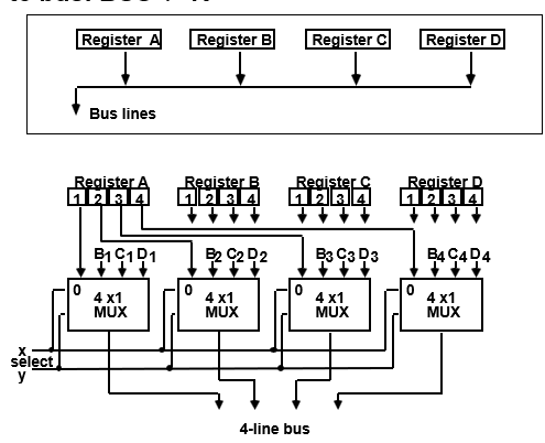
Bus & Memory Transfer
A digital computer has many registers and rather that connecting wires between all registers to transfer information between them, a common bus is used.
Bus is a path over which info is transferred from any of several sources to any of several destination.
From a register to Bus :
From Bus to Register :
Types of Bus:
- Data Bus
- A data bus carries data.
- It is an electrical path that connects CPU, memory, I/O devices and secondary storage.
- The bus contain parallel group of lines.
- The number of lines in bus affect the speed.
- Address Bus
- An address bus carries address information.
- It is set of wired similar to the data bus but it only connects CPU and memory.
- Whenever the processor needs data from the memory, it places the address of data on the address bus.
- The address is carried to the memory where the data from the requested address is fetched and placed on the data bus.
- Control Bus
- The control bus carries control information from the control unit to the other units
- The control information is used for directing the activities of all units
- The control unit control the functioning of other units, ex : input/output devices, etc..
Bus Arbitration
Bus master: The device that is allowed to initiate data transfer on the bus at any given time is called data bus master.
Bus arbitration is the process by which the next device to become the bus muster is selected and bus mastership is transferred to it. Selecting of bus master is usually done on priority basis.
There are two approaches
- Centralized arbitration
- Distributed arbitration
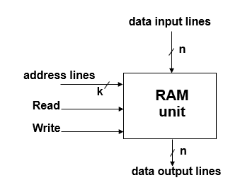
Memory (RAM)
- sequential circuits containing some number of registers
- this registers hold the words of memory
- each of the r register is indicated by an address
- these addresses range from 0 to r-1
- each register can hold n bits of data
- Ram contains r = 2k words
- n - data input line
- n data output line
- k address lines
- a read control line
- a write control line
Memory is usually accessed in computer by putting desired address in a special register, Memory Address Register (MAR or AR)
When memory is accessed, the contents of the MAR send to the memory unit’s address lines.
Memory read:
- the contents of the MAR get sent to the memory address lines
- Read = 1
- The contents of the address are put on the memory’s output data lines
- these get sent over the bus to be loaded into register R1
Memory write :
- The contents of the MAR get sent to the memory address lines
- Write = 1
- The values of R1 get sent over the bus to the data input lines of the memory
- the values get loaded into the specified address in the memory
–cil for a circular shift left
–cir for a circular shift right
–ashl for an arithmetic shift left
–ashr for an arithmetic shift right
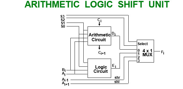
hardware implementation for shift microoperation

Out of Syllabus
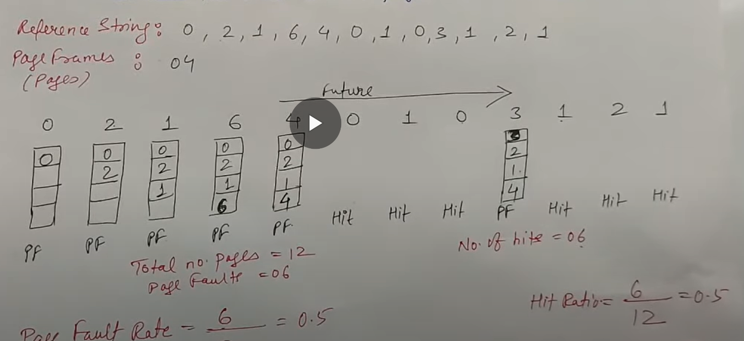
Page Replacement Algorithm
Page Replacement Algorithm decides which memory page to page or page-out (swap-out, write to disk) when a page of memory needs to be allocated.
When a program starts execution
- one or more pages transferred into main memory and
- the page-table is set to indicate their position
The program is executed from main memory until it attempts to reference a page that is still in auxiliary or secondary memory. This is called Page Fault.
Page Fault: If the required page is not present in main memory the page fault occurs, which requires I/O operation.
The goal of a replacement policy is to try to remove the page that least likely to be referenced in the immediate future.
Some Replacement Policies:
- FIFO
- First-in-First-out
- it is easy to implement
- it selects the page for replacement that has been in memory for longest time
- Oldest page in memory is selected by replacement
- It keeps a list and replace page from tail add new page at the head
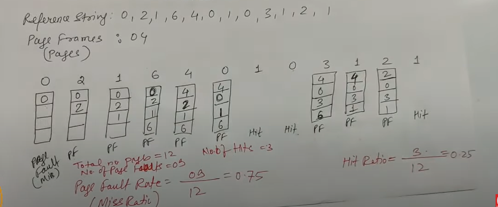
Page frames : number of pages that it can store in memory
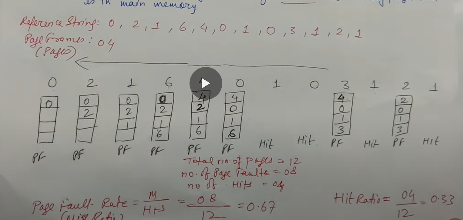
- LRU
- Least Recently Used
- LRU selects a page for replacement which has not be used for the longest time in main memory
- It keeps a list and replace page by looking back into time
- It is implemented associating a counter with every page that is is main memory
- Optimal Page Replacement Algorithm
- It has lowest page fault rate of all algorithm
- Optimal policy replace the page that will not be used for the longest period of time
- It uses the time when a page is to be used next